

 0
0
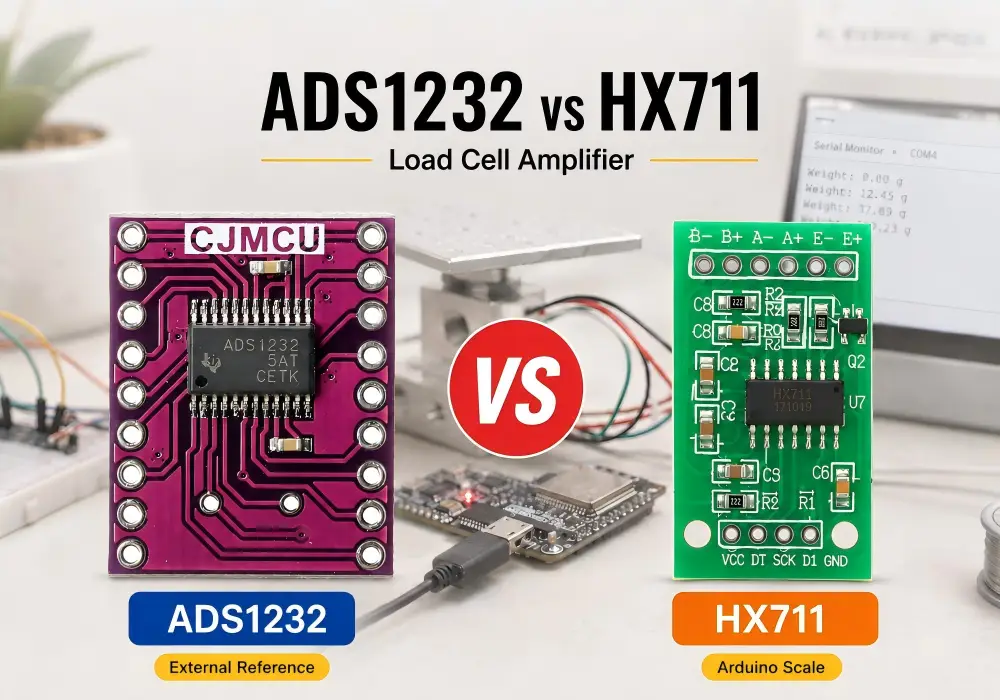
ADS1232 and HX711 are both 24-bit delta-sigma converters commonly used with strain gauges, Wheatstone bridges and load cells. On a product page, their specifications can look surprisingly similar. In a real weighing system, however, the quality of the result depends on much more than the advertised number of bits.
Recent maker and engineering discussions reveal a consistent pattern. Users are not simply looking for more resolution. They want to eliminate unstable readings, reduce zero drift, avoid long averaging delays and understand whether upgrading from an HX711 load cell amplifier to an ADS1232 will produce a measurable improvement.
This ADS1232 vs HX711 guide compares their architecture, sample rate, gain, reference design, noise behavior and integration with Arduino, ESP32 and STM32. For a broader comparison of precision ADC modules, also read our ADS1256 vs ADS1232 vs ADS1220 guide.
1. ADS1232 vs HX711: The Quick Answer
Choose HX711 for Simple and Affordable Scales
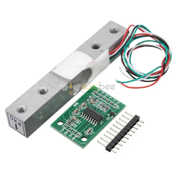
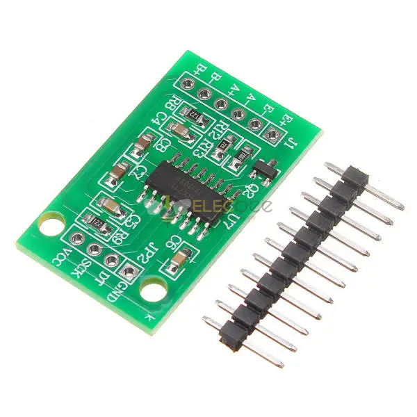
The HX711 is usually the better starting point when cost, availability and software simplicity matter most. It is widely supported by Arduino and ESP32 libraries, and many modules can connect directly to a four-wire load cell using excitation, differential signal, clock and data connections.
An HX711 load cell system is suitable for:
- Kitchen, postal and bench scales
- Arduino and ESP32 learning projects
- 1 kg, 5 kg and 20 kg DIY weighing systems
- Basic force and pressure experiments
- Projects where 10 or 80 samples per second is sufficient
A properly mounted load cell and a well-powered HX711 can deliver stable, repeatable results. Replacing it simply because the output code moves by a few counts is rarely the best first step.
Choose ADS1232 for Greater Signal-Chain Control
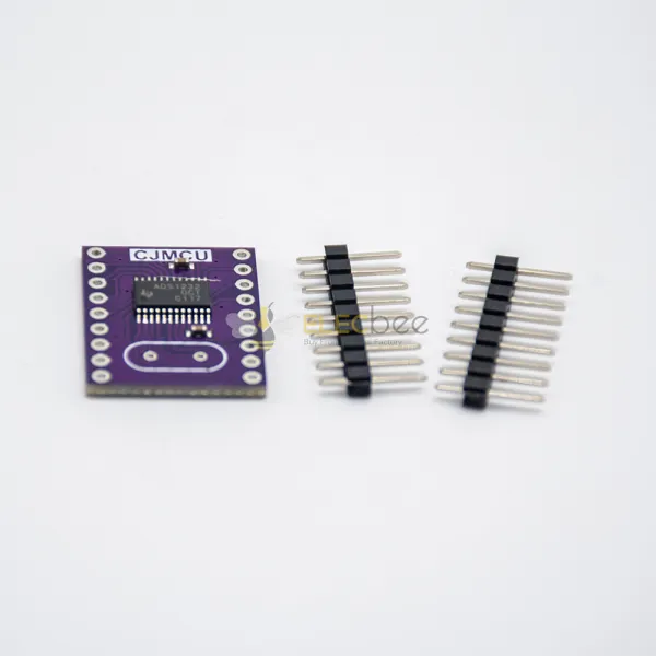
The ADS1232 is designed specifically for bridge sensors and provides two differential input channels, selectable gains of 1, 2, 64 and 128, and an external differential reference input. Its reference architecture makes it attractive for ratiometric measurements in which the same stable source excites the load cell and defines the ADC reference.
Consider the ADS1232 when your project requires:
- Greater control over bridge excitation and reference voltage
- Two differential sensor inputs
- Strong low-frequency mains rejection at the 10 SPS setting
- System-level offset calibration
- Careful evaluation of sub-gram changes across a moderate load range
- A purpose-designed PCB rather than a basic prototyping board
The ADS1232 can support a more controlled measurement system, but it does not automatically correct a low-quality load cell, incorrect mounting or a noisy power supply.
Neither ADC Is Designed for High-Speed Acquisition
Both the ADS1232 and HX711 normally offer 10 SPS and 80 SPS output-rate options. At 10 SPS, a new sample arrives approximately every 100 milliseconds. At 80 SPS, the interval falls to approximately 12.5 milliseconds before additional software filtering is applied.
If a force pedal, impact test, vibration system or dynamic press requires hundreds or thousands of samples per second, neither device is an ideal choice. Select a faster ADC with an appropriate instrumentation amplifier and anti-aliasing filter instead of trying to force a weighing ADC beyond its intended operating range.
2. How ADS1232 and HX711 Handle Load Cell Signals
24-Bit Resolution Versus Real Measurement Accuracy
A 24-bit output contains up to 16,777,216 digital codes. This does not mean that a scale can resolve one part in 16 million with stable, calibrated accuracy.
Usable performance is limited by:
- Input-referred ADC noise
- Load cell sensitivity and rated output
- Bridge excitation stability
- Reference voltage noise and drift
- Mechanical creep and hysteresis
- Temperature changes
- Power supply and ground interference
- PCB layout, wiring and electromagnetic interference
The correct question is not “Which ADC has more bits?” Both have a nominal 24-bit output. The useful question is “Which complete signal chain produces the lowest repeatable error across the required measurement time, load range and temperature?”
Channels, Gain and Voltage Reference
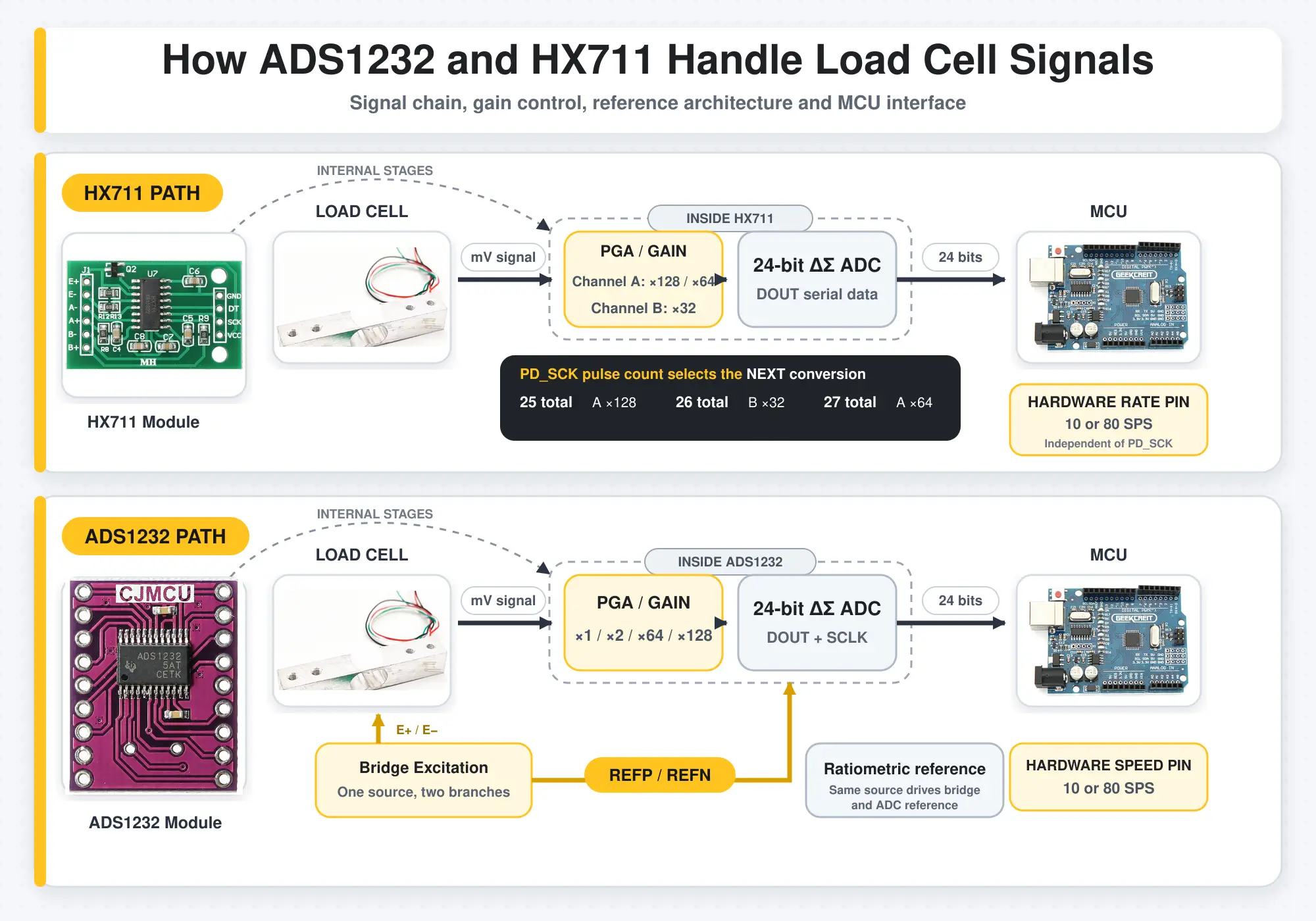
The HX711 contains two input channels. Channel A normally supports gains of 128 or 64, while Channel B uses a gain of 32. The channel and gain used for the next conversion are selected by sending one, two or three additional PD_SCK pulses after the 24-bit conversion result has been read.
- 25 total PD_SCK pulses select Channel A with a gain of 128.
- 26 total PD_SCK pulses select Channel B with a gain of 32.
- 27 total PD_SCK pulses select Channel A with a gain of 64.
The RATE pin controls only the output data rate. It does not select the HX711 input channel or gain.
The ADS1232 also provides two differential inputs and offers gains of 1, 2, 64 and 128. At gains of 1 and 2, the ADS1232 bypasses the high-gain PGA path, making these settings useful for larger differential inputs and signal-chain testing. Gains of 64 and 128 are better suited to the low-level outputs produced by load cells and other bridge sensors.
A major architectural difference is the reference design. The ADS1232 exposes dedicated REFP and REFN pins, allowing the load cell excitation voltage to serve directly as a differential conversion reference. This gives the designer clear control over external reference filtering and ratiometric bridge measurement.
The HX711 does not expose separate reference input pins. Its conversion reference follows the analog supply, and common designs power the load cell bridge from the same AVDD rail, which can also provide ratiometric behavior. The chip includes a regulator control circuit that can drive an external PNP pass transistor, but the actual regulator, filtering and bridge-excitation implementation varies between breakout boards.
10 SPS, 80 SPS and Measurement Latency
The 10 SPS setting is normally preferred for static weighing because it offers lower noise and better rejection of 50 Hz and 60 Hz interference. The 80 SPS setting improves response time but generally increases noise.
Software filters add another layer of latency. For example, averaging 16 samples at 10 SPS requires approximately 1.6 seconds of data. The output may look smooth, but a fast change in load will appear late.
Averaging N independent samples can reduce random noise by approximately the square root of N. It cannot remove load cell creep, thermal drift, reference instability, electromagnetic interference or a saturated amplifier.
3. ADS1232 vs HX711 Comparison
Side-by-Side Specifications
| Feature | HX711 | ADS1232 | Practical Effect |
|---|---|---|---|
| Architecture | 24-bit delta-sigma ADC | 24-bit delta-sigma ADC | Nominal resolution alone does not determine accuracy |
| Inputs | Two channels | Two differential channels | Both support two signal paths, but their channel and gain options differ |
| Gain | Channel A: 64 or 128; Channel B: 32 | 1, 2, 64 or 128 | ADS1232 offers more flexibility for larger signals and system testing |
| Output rate | 10 or 80 SPS | 10 or 80 SPS | Neither is intended for high-speed waveform capture |
| Reference approach | Conversion reference follows AVDD; module implementation varies | Dedicated external differential reference inputs | ADS1232 provides more explicit control of external reference and ratiometric measurement |
| Configuration | Gain and channel for the next conversion are selected through 25, 26 or 27 total PD_SCK pulses; RATE pin selects speed | Dedicated hardware pins select gain, speed and channel; offset calibration is initiated through the serial clock sequence | HX711 combines data readout with next-conversion selection, while ADS1232 separates most configuration controls from readout |
| Software ecosystem | Broad Arduino and ESP32 library support | Fewer ready-made libraries | HX711 is generally easier for beginners |
| Best fit | Affordable scales and DIY load cell kits | Controlled low-noise bridge measurement | Choose according to the complete system, not the ADC name |
What the Differences Mean in Practice
The HX711 wins on cost, availability and development speed. It is easy to find tested example code, calibration libraries and complete sensor kits. For a normal digital scale, these advantages can be more valuable than the additional configuration options of the ADS1232.
The ADS1232 becomes more attractive when you are designing the analog section rather than simply connecting a module. Its external differential reference, selectable gains and calibration controls allow the bridge, reference, power supply and PCB layout to be treated as one measurement system.
However, an ADS1232 on unshielded perfboard can perform worse than a well-designed HX711 PCB. At microvolt signal levels, bypass capacitors, grounding, connector quality, thermal gradients and cable movement all affect the result.
Recommended Module and Load Cell Configurations
| Project | Recommended Configuration | Reason |
|---|---|---|
| Existing load cell | HX711 24-bit load cell amplifier module | Lowest-cost way to add digital conversion |
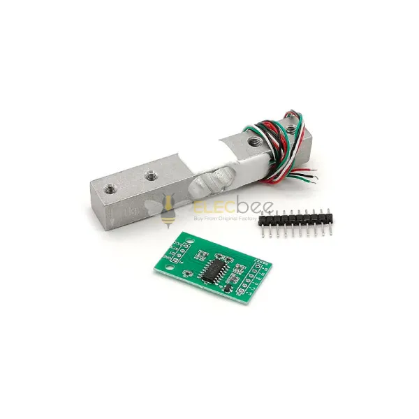
| Small precision scale | 1 kg HX711 load cell kit | Suitable range for small objects and compact platforms |
| General DIY scale | 5 kg load cell with HX711 module | Balanced capacity for kitchen, bench and prototype scales |
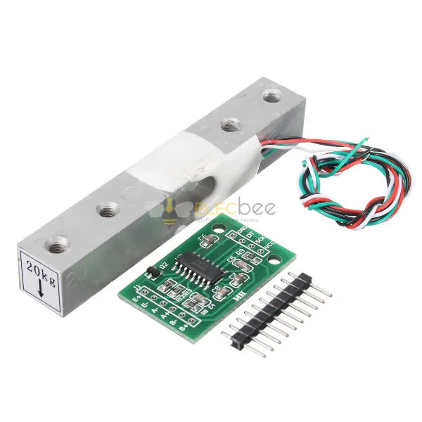
| Higher-capacity platform | 20 kg HX711 load cell kit | Greater capacity for packages, tools and equipment |
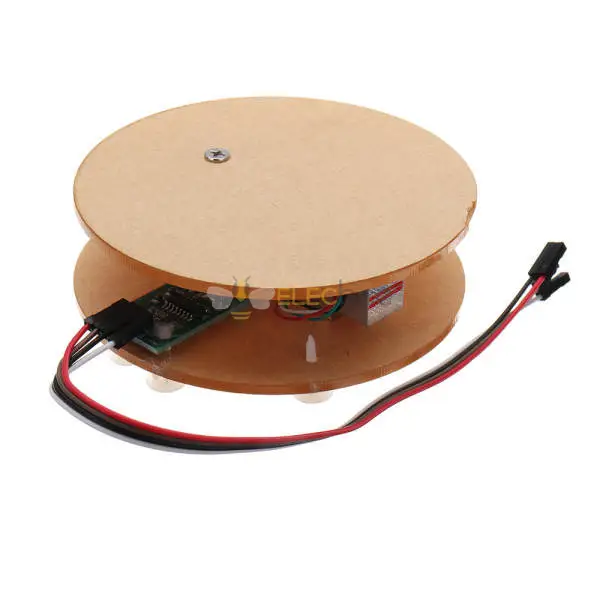
| Compact assembled scale | 5 kg load cell scale module with shell | Provides a more complete mechanical structure |
| Custom low-noise bridge system | ADS1232 24-bit ADC board | Better reference, gain and calibration control |
4. Why HX711 Load Cell Readings Become Noisy or Unstable
Mechanical Mounting and Load Cell Creep
Many unstable HX711 readings are mechanical rather than electronic. A bar-type load cell normally has a fixed end and a loading end. Incorrect orientation, loose screws, uneven spacers or a platform that touches the enclosure can make the output nonlinear or unstable.
The load cell cable should usually leave from the stationary side. If the cable pulls on the moving section, every movement of the cable becomes part of the measurement.
Load cells also exhibit creep. After applying a constant load, the output may continue changing slowly as the metal and adhesive settle. Software averaging cannot remove this physical effect.
Power, Grounding, Wiring and Interference
A load cell produces a small differential signal, often measured in millivolts at full rated load. Long unshielded wires, breadboard contacts and switching power supplies can therefore introduce significant error.
Use short signal paths, secure solder joints and twisted pairs for remote sensors. For longer cables, shielded wiring can help, but connect the shield according to the grounding strategy rather than treating it as an additional signal conductor.
Place bypass capacitors close to the ADC supply pins. Keep DC-DC converters, relays, displays, motors, SPI clocks and wireless antennas away from the bridge input. For an ADS1232 load cell design, route the reference and excitation connections carefully and confirm that the selected module supports the intended ratiometric connection.
Filtering, Tare Timing and Wireless Interference
A moving average can reduce random jitter, but a large averaging window makes the scale slow. Median filters can suppress occasional spikes, while low-pass filters can smooth continuous noise. No filter should be used to hide a loose connection, saturated input or unstable reference.
Perform tare only after the mechanics, ADC and power supply have settled. An arbitrary startup delay may work in one environment and fail after the temperature, power source or load cell changes.
ESP32 Wi-Fi and LoRa transmitters can couple interference through the power rail, ground plane or nearby wiring. Record raw readings with the radio disabled and enabled. If the difference is measurable, improve supply isolation, layout and measurement timing rather than relying only on firmware averaging.
Board layout, power regulation and wireless features vary between ESP32 models. If you are building a connected weighing system, see our guide on choosing the best ESP32 board for an IoT project.
| Symptom | Likely Cause | Diagnostic Test | Recommended Fix |
|---|---|---|---|
| Slow zero drift | Warm-up, temperature or load cell creep | Record unloaded data for several minutes | Allow settling and improve temperature stability |
| Random jumps | Loose connector, cable movement or EMI | Move the cable and switch nearby devices on and off | Solder connections, secure the cable and add shielding |
| Stable but inaccurate | Poor calibration, mounting or load cell nonlinearity | Test zero, midpoint and near-full-scale loads | Use multi-point calibration and correct the mechanics |
| Excessive response delay | 10 SPS operation or excessive averaging | Compare raw and filtered timestamps | Select 80 SPS and reduce the filter window if noise permits |
| Software rate setting has no effect | RATE is tied to GND through a 0-ohm resistor, solder bridge or PCB trace | Inspect the module schematic, RATE pad and resistor connections | Where supported, move or remove the link and pull RATE to DVDD; do not leave RATE floating |
| Noise rises during Wi-Fi or LoRa transmission | Supply, ground or RF coupling | Compare radio-on and radio-off raw data | Improve power isolation, layout and measurement timing |
5. How to Test an HX711 or ADS1232 Load Cell System
Mount and Wire the Load Cell Correctly
- Identify the fixed end and loading end of the load cell.
- Mount both ends on rigid, flat surfaces using the correct spacers.
- Ensure the weighing platform does not touch the frame or enclosure.
- Route the cable from the stationary end and add strain relief.
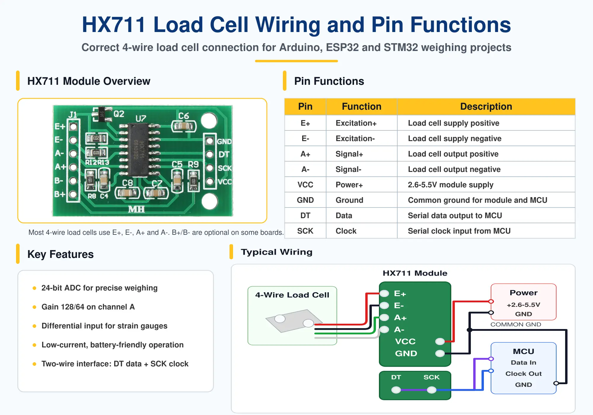
- Connect excitation positive and negative to the bridge supply.
- Connect signal positive and negative to the differential ADC input.
- Confirm supply voltage, logic levels and grounding before powering the module.
- For ADS1232 ratiometric operation, verify the module schematic before connecting the bridge excitation to the differential reference input.
Measure Baseline Noise and Drift
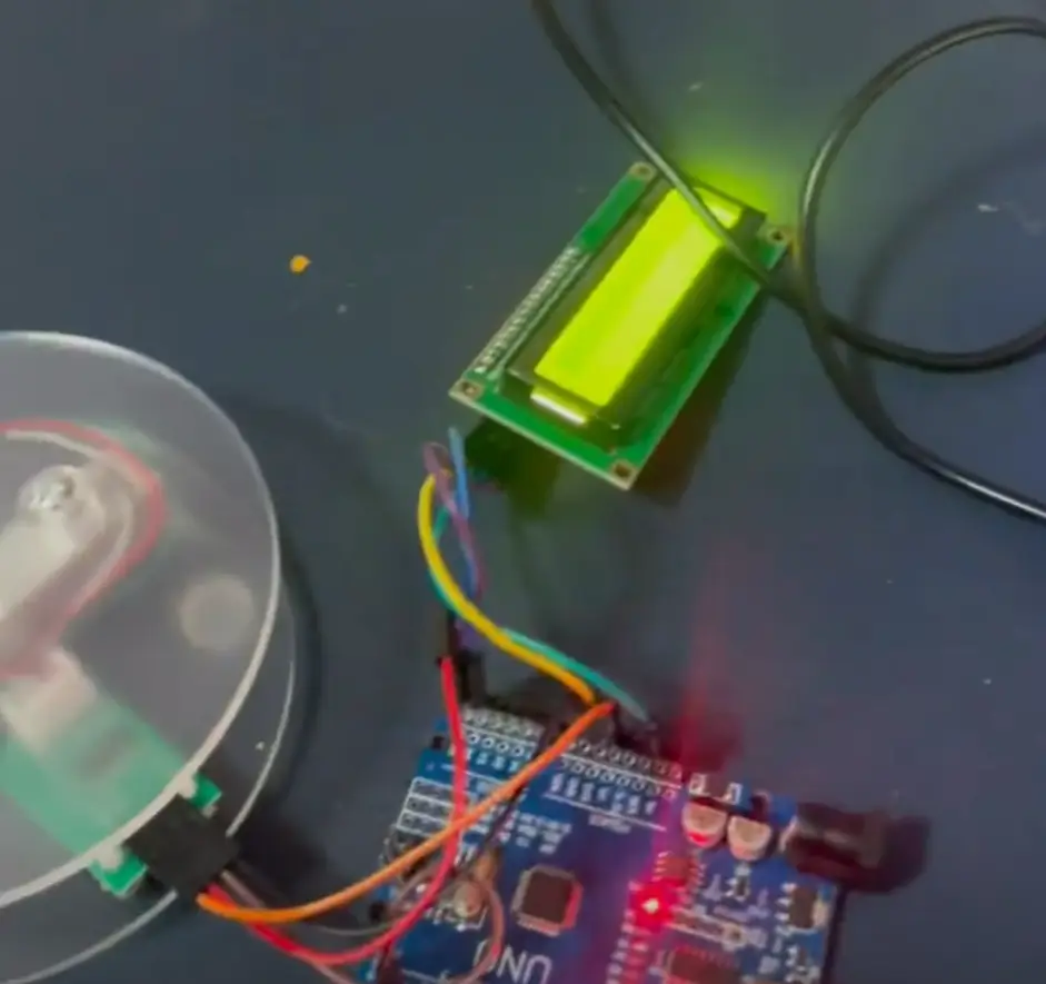
Begin at 10 SPS with no load on the platform. Record raw, unfiltered codes for several minutes after warm-up. Calculate or log:
- Mean raw code
- Standard deviation
- Peak-to-peak variation
- Change in the mean over time
- Temperature, supply voltage and radio state
Next, apply a stable weight and repeat the test. A good system should not only produce a small zero variation; it should also return to approximately the same zero after the weight is removed.
Repeat the measurement with displays, relays, Wi-Fi, Bluetooth or LoRa enabled. This separates ADC noise from interference generated by the rest of the system.
Calibrate and Compare Both ADCs Fairly
A basic linear calibration uses:
Weight = (raw reading − zero offset) ÷ calibration factor
Determine the zero offset with an unloaded platform. Apply a known calibration mass and calculate the factor from the change in raw code. For better accuracy, test several weights across the intended range instead of relying on a single calibration point.
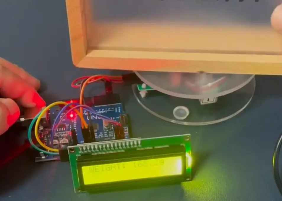
When comparing ADS1232 vs HX711, keep the following conditions identical:
- The same load cell and mounting structure
- The same excitation voltage where the architecture permits
- The same sample-rate setting
- The same test weights and ambient conditions
- Raw data before software filtering
- The same measurement duration
Compare standard deviation, peak-to-peak noise, zero return, drift and response time. Do not judge the result only by how smooth a displayed number appears.
6. Which ADC Fits Your Application?
Low-Cost Arduino Digital Scale
For a kitchen scale, parcel scale or general Arduino weighing project, an HX711 load cell kit is usually the most practical choice. Libraries are widely available, the wiring is simple and complete kits reduce uncertainty about sensor capacity.
Select a load cell whose rated capacity is reasonably close to the maximum expected load. A 20 kg load cell used only for measuring a few grams produces a much smaller signal change per gram than a properly selected 1 kg sensor.
Arduino is usually easier for a first weighing project, while STM32 provides greater control for more advanced embedded designs. Read our STM32 vs Arduino beginner comparison if you are still choosing a development platform.
Sub-Gram ESP32, STM32 or IoT Scale
For a 2 kg or 3 kg system targeting sub-gram repeatability, the load cell, mechanics, reference and PCB layout become as important as the ADC.
If you are deciding between wireless connectivity and more traditional embedded control, our STM32 vs ESP32 comparison explains the main differences in processing, connectivity, development workflow and IoT integration.
An ADS1232 can be a strong choice when the design uses ratiometric bridge excitation, controlled grounding, short differential traces and proper decoupling. Before changing ADCs, test whether the current HX711 error is correlated with cable movement, temperature, radio transmission or power supply changes.
If a stable HX711 system still fails the required noise and drift limits under controlled conditions, the ADS1232 provides a sensible upgrade path. If the mechanics are responsible, the same problem will remain after the upgrade.
Fast Force, Pedal and Impact Measurement
For a load cell pedal or force-control interface, 10 SPS can feel delayed. Changing the HX711 RATE setting to 80 SPS and reducing the averaging window may improve response substantially.
HX711 RATE warning: Many common HX711 breakout boards tie the RATE pin to GND through a 0-ohm resistor, solder bridge or PCB trace, fixing the module at 10 SPS. Software alone cannot select 80 SPS. Check the module schematic and, where supported, move or remove the link and pull RATE to DVDD. Do not leave the RATE pin floating.
After changing the hardware rate, verify the actual interval between data-ready events. Different breakout boards may use different resistor positions, solder pads or routing arrangements.
If the application needs reliable acquisition above 80 SPS, select a faster ADC and instrumentation amplifier. High sample rate, low latency and precision static weighing are different design goals.
Recommended starting points
Choose the HX711 load cell amplifier module for an affordable Arduino scale or use a matched 1 kg, 5 kg or 20 kg kit when you also need the sensor.
Choose the ADS1232 low-noise ADC board when the design requires greater control over gain, external differential reference and ratiometric bridge measurement.
7. FAQ and Final Recommendation
Common ADS1232 vs HX711 Questions
Is ADS1232 more accurate than HX711?
The ADS1232 provides more signal-chain control and is designed for bridge sensors, but it is not automatically more accurate in every project. Load cell quality, mounting, excitation, reference, PCB layout and calibration determine the final result.
Can ADS1232 directly replace HX711?
No. They are not pin-compatible and do not use the same software interface. The ADS1232 requires different configuration, wiring and calibration handling. Review the module schematic and update the firmware before replacing an HX711.
Why does my HX711 reading move by one or two grams?
Possible causes include an oversized or low-quality load cell, incorrect mounting, cable force, noisy power, loose connections, temperature drift, vibration or insufficient settling time. Test raw codes before adding more averaging.
Should I use 10 SPS or 80 SPS?
Use 10 SPS for static weighing, lower noise and better mains rejection. Use 80 SPS when faster response is more important and the resulting increase in noise is acceptable. On many breakout boards, selecting 80 SPS requires changing the hardware connection of the RATE pin.
Can either ADC measure high-speed force changes?
Both officially reach 80 SPS. If the signal contains important content above this range, use a faster ADC with a suitable analog front end and anti-aliasing filter.
Load Cell ADC Buying Checklist
- Maximum load and required smallest detectable change
- Static weighing or dynamic force measurement
- Required sample rate and acceptable latency
- Load cell rated output and bridge resistance
- Input gain and common-mode requirements
- Reference voltage and excitation architecture
- Mechanical mounting and overload protection
- Cable length, shielding and grounding
- Arduino, ESP32 or STM32 software support
- Calibration, temperature and long-term drift requirements
Final Recommendation
Choose HX711 for a cost-effective Arduino or ESP32 scale, especially when you want a complete HX711 load cell kit and broad library support. It remains an effective solution when the sensor is mounted correctly, the power is clean and the filtering matches the required response time.
Choose ADS1232 for a more controlled bridge measurement system requiring an external differential reference, flexible gain settings, two differential inputs and deliberate low-noise design. Its advantages become meaningful when the entire analog signal chain is designed to use them.
Do not upgrade based only on the 24-bit label or a noisy display. First measure raw noise, drift and zero return; correct mechanical and electrical problems; then compare both converters under identical conditions. The best load cell amplifier is the one that meets the real error and response requirements of the complete weighing system.
Recommended HX711 Load Cell Modules and Kits
Browse HX711 weighing modules, load cell amplifier boards and sensor kits for Arduino DIY scales, smart weighing systems and force measurement projects.