

 0
0
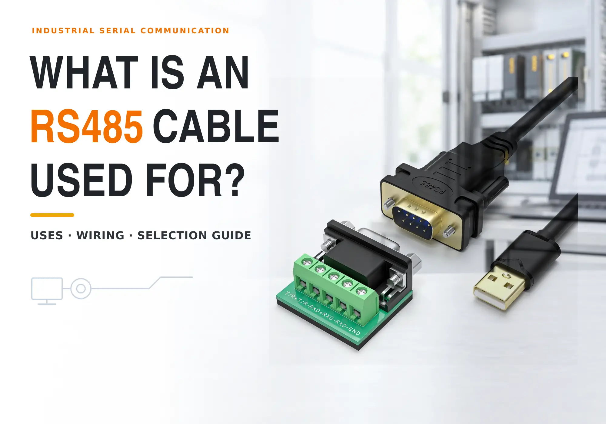
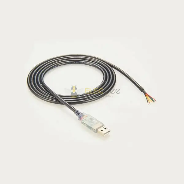
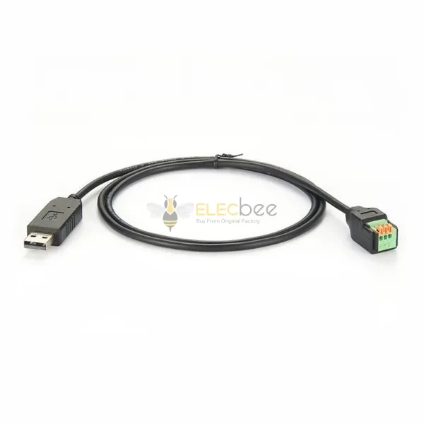
An RS485 cable carries differential serial data between controllers, sensors, drives, meters, building-automation devices, and other equipment that must communicate reliably over a shared bus. The familiar name is written both as RS485 and RS-485. In practice, a purpose-built cable usually combines a twisted data pair, controlled impedance, suitable conductor size, and—where the electrical environment demands it—a shield and industrial jacket.
Choosing a cable by label alone is not enough. Reliable communication also depends on topology, termination, biasing, grounding, baud rate, total cable length, stub length, connector pinout, and the transceivers at both ends. This guide explains what an RS485 cable is used for, how to choose a Modbus RS485 cable, how to wire the bus, and how to diagnose a network that works on the bench but fails in the field.
Quick answer
- Use one twisted pair for the differential A/B data path in a typical 2-wire, half-duplex network.
- Choose cable with a characteristic impedance that matches the network design; nominal 120-ohm cable is common for RS485.
- Build a linear trunk with short stubs and terminate only the two physical ends of each bus segment.
- Treat signal reference, cable shield, and protective earth as three different design decisions.
- Confirm every device manual because A/B naming, pinouts, internal termination, and internal biasing are not universal.
1. What Is an RS485 Cable?
RS485 Is a Physical Layer, Not a Protocol
RS485 defines the electrical characteristics of drivers and receivers used for balanced, multipoint serial communication. It does not define the meaning of a message, a universal connector, or a universal pinout. Protocols such as Modbus RTU, BACnet MS/TP, and some proprietary control systems can use an RS485 physical layer, but they organize data in different ways.
This distinction prevents a common purchasing mistake. A cable can be electrically suitable for RS485 without being “a Modbus cable,” while a device advertised as Modbus-compatible may still require you to determine the correct pair, connector, pinout, termination, and grounding method.
2-Wire vs 4-Wire RS485
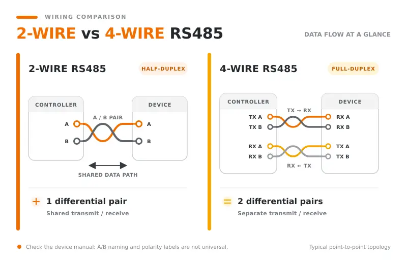
Most modern field networks use a 2-wire, half-duplex bus. The same twisted pair carries traffic in both directions, so only one transmitter should control the pair at a time. A 4-wire network uses separate transmit and receive pairs and can support full-duplex communication, but it needs compatible devices and more conductors.
| Feature | 2-Wire RS485 | 4-Wire RS485 |
|---|---|---|
| Data pairs | One bidirectional pair | Separate transmit and receive pairs |
| Communication | Half-duplex | Full-duplex or four-wire master/slave arrangement |
| Typical use | Multipoint industrial and building-control buses | Legacy or specialized systems that specify four-wire operation |
| Selection caution | Check automatic or software-controlled transmit direction | Check which pair is TX and which is RX at every device |
Why Twisted-Pair Cable Matters
The receiver detects the voltage difference between the two conductors. Twisting exposes both conductors to similar external noise, allowing much of that coupled noise to be rejected as common-mode interference. Controlled impedance also limits signal reflections when the cable is terminated correctly.
Untwisted hookup wire may appear to work across a short bench setup, yet become unreliable when the cable is longer, the data rate increases, more nodes are connected, or a variable-frequency drive and motor cables are installed nearby. The objective is not simply to make packets pass today; it is to preserve enough signal margin for changing temperature, equipment states, and electromagnetic conditions.
2. What Is an RS485 Cable Used For?
Industrial Automation and Machine Control
Factories use RS485 links to connect PLCs, operator panels, remote I/O, variable-frequency drives, servo systems, weigh scales, barcode readers, and instruments. A multipoint bus can connect several devices along a production line without requiring a dedicated point-to-point serial cable for every node.
RS485 remains useful where equipment must tolerate electrical noise, span distances beyond a local equipment rack, and operate with simple deterministic serial protocols. It also provides a practical bridge between modern computers and installed machinery through USB-to-RS485 or Ethernet-to-RS485 gateways.
Building Automation, HVAC, Energy, and Environmental Monitoring
Common applications include HVAC controllers, room sensors, heat meters, power meters, access-control panels, elevators, battery systems, solar inverters, generators, and environmental monitoring. Many of these systems use Modbus RTU or BACnet MS/TP over an RS485 bus because multiple field devices can share one cable route.
Outdoor, plant-room, and rooftop installations add cable-selection requirements. Temperature range, UV exposure, moisture, oils, flexing, flame rating, local electrical codes, and surge exposure may matter as much as the data-pair specification.
Lighting, Access Control, and Distributed Devices
RS485 can also link lighting controllers, addressable signs, security panels, ticketing equipment, laboratory instruments, and distributed embedded systems. It is especially useful when devices exchange relatively small, periodic messages rather than high-bandwidth media.
Field Case: A Bus That Worked for Years Before Failing
An anonymized field discussion described a plant network that had operated for roughly five years before intermittent communication faults became severe. An oscilloscope revealed reflections, and the terminator at a drive had been left disabled. Enabling the correct end termination restored a much cleaner waveform.
The lesson is not that termination alone explains every failure. It is that an RS485 bus can run with limited margin for a long time. Cable aging, a replaced device, a new noise source, an altered route, or a small change in loading can expose a topology or termination error that was present from day one.
3. RS485 Cable vs RS232 Cable vs Ethernet Cable
Key Differences at a Glance
| Criterion | RS485 | RS232 | Copper Ethernet |
|---|---|---|---|
| Signaling | Balanced differential | Single-ended | Balanced differential pairs |
| Typical topology | Linear multipoint bus | Point-to-point | Switched point-to-point links |
| Normal reach | Long field runs at suitable data rates | Short equipment-to-equipment links | Defined channel limits for the selected Ethernet category |
| Nodes | Multiple devices per properly designed segment | Normally two devices | One device per switch port/link |
| Typical cable | Often nominal 120-ohm twisted pair | Multiconductor serial cable | Usually 100-ohm category cable with four pairs |
| Interchangeable? | No; electrical layer and pinout must match | No; requires an active converter for RS485 | Not automatically; cable and network electronics serve different standards |
When Each Interface Makes Sense
Choose RS232 for a simple, short, point-to-point connection when both devices already provide compatible RS232 ports. Choose RS485 when several field devices need to share a robust serial bus or when the run is too demanding for a single-ended link. Choose Ethernet when the application needs IP networking, higher bandwidth, switch-based infrastructure, or integration with enterprise systems.
For a deeper interface comparison, read RS232 vs RS485 vs RS422: Key Differences in Distance, Speed & Wiring. If the project uses a legacy point-to-point port, What Is an RS232 Cable Used For? Applications, Types and Selection Guide explains RS232 cable types and selection in more detail.
Can an RS232 Cable Be Reused for RS485?
Physical reuse is possible only after confirming the cable construction, pair arrangement, impedance, capacitance, conductor size, shielding, length, and environment. A DB9 connector does not make a cable electrically suitable, and RS485 has no universal DB9 pinout. An active RS232-to-RS485 converter is also required because the signaling voltages and driver behavior are different.
4. How to Choose the Right RS485 or Modbus Cable
Start With Impedance, Twisting, and Capacitance
For a conventional RS485 bus, begin with a cable specified as a balanced twisted pair with nominal 120-ohm characteristic impedance. Match the termination resistance to the cable and transceiver recommendations. Consistent impedance through cable, connectors, and junctions is more important as edge rates increase and branches become electrically long.
Low-capacitance cable can help preserve rise time on long runs. Do not evaluate baud rate alone: a transceiver may switch with faster edges than the bit period suggests, which is why a seemingly slow network can still suffer from reflections.
Size Conductors for Length, Reference, and Power
Longer runs and installations that also distribute low-voltage power may require larger conductors to control voltage drop. If the system needs a signal-reference conductor, include it deliberately rather than substituting the shield. When power and data share one overall cable, verify conductor ratings, isolation, current, voltage drop, and the equipment manufacturer's wiring instructions.
Do not place low-voltage communications in the same conduit or bundle as hazardous or high-power conductors unless the cable ratings, local code, and equipment documentation explicitly permit it. Maintain practical separation from motor leads and VFD output cables.
Select Shield and Jacket for the Installation
A shield may improve electromagnetic compatibility near drives, contactors, motors, welding equipment, and radio transmitters, but it does not correct a poor bus topology. Select foil or braid coverage, drain wire, oil resistance, UV resistance, flex rating, temperature range, and flame rating according to the site.
Decide how the shield will be bonded as part of the system EMC design. Avoid treating the shield as the normal signal-return conductor. In facilities with substantial ground-potential differences, isolated transceivers or isolated repeaters may be safer and more reliable than trying to force distant equipment grounds to the same potential through a data cable.
Check Connectors, Pinouts, Protection, and Converters
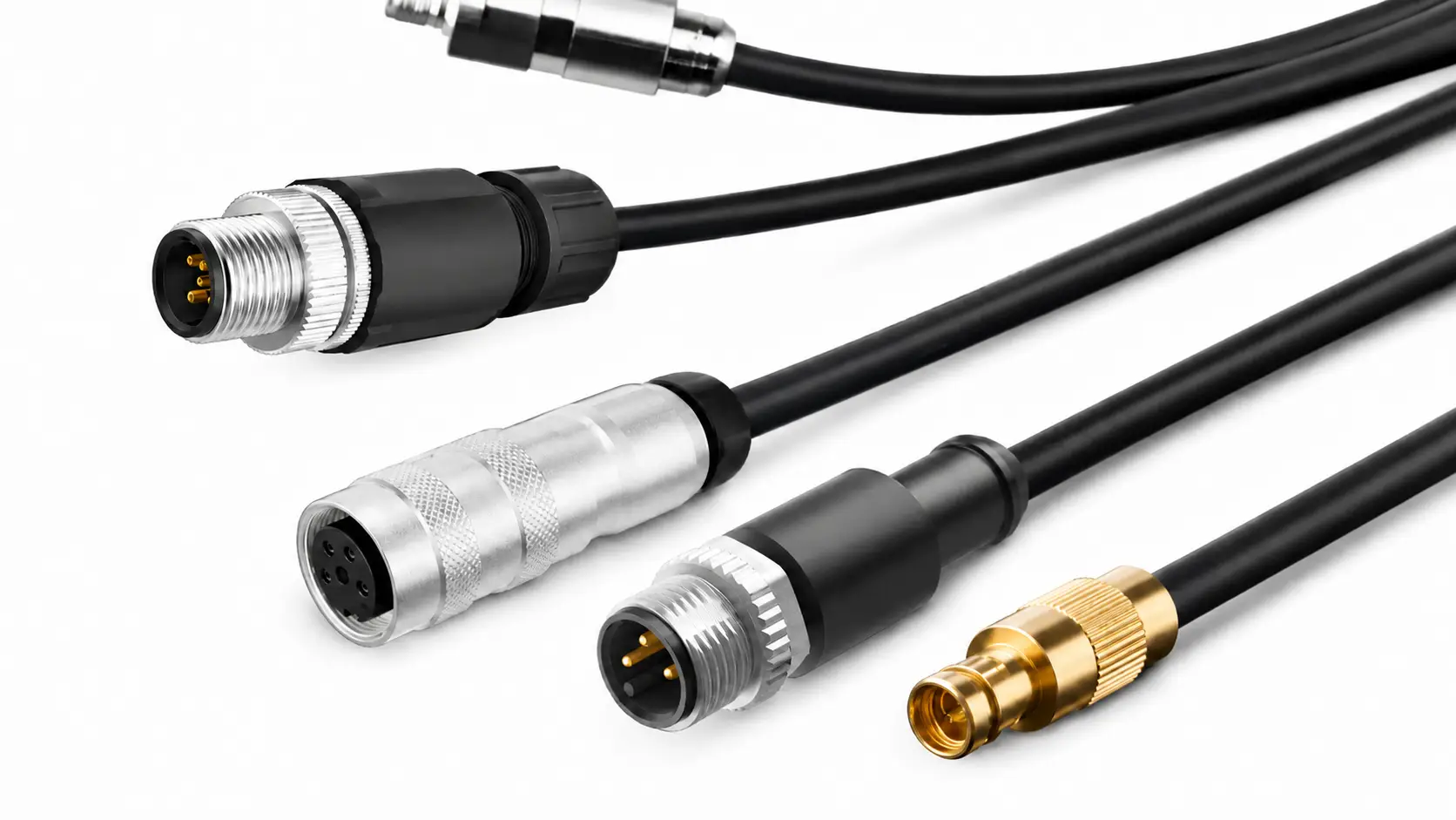
RS485 may appear on screw terminals, pluggable terminal blocks, DB9, RJ45, M8, M12, or proprietary connectors. Confirm the exact pinout and polarity at both devices; never assume two matching connector shells use the same assignments. For sealed industrial equipment, Elecbee M12 connector technology provides useful background on rugged circular interconnects.
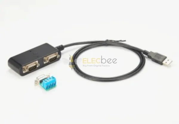
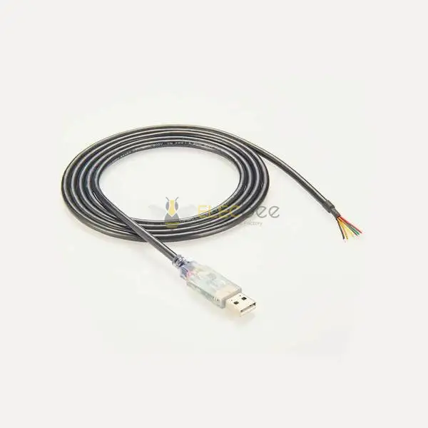
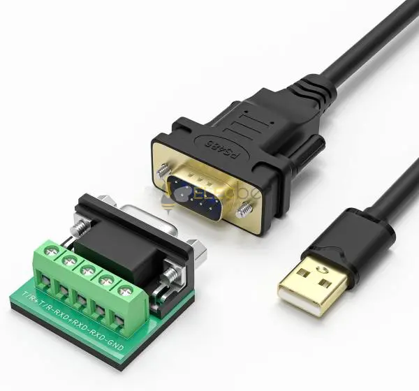
Modern interfaces increasingly combine galvanic isolation, surge or ESD protection, integrated fail-safe behavior, and automatic transmit-direction control. These features can simplify a design, but they do not eliminate cable or topology rules. When connecting a computer, verify the converter's isolation, supported data rate, driver compatibility, terminal labeling, and direction-control method; relevant options can be explored under Smart Cables.
| Selection Item | What to Confirm | Why It Matters |
|---|---|---|
| Data pair | Twisted, balanced, nominal impedance, capacitance | Controls noise pickup and reflections |
| Conductors | Gauge, strand type, reference wire, optional power cores | Affects voltage drop, flex life, and installation |
| Environment | Noise, temperature, moisture, oil, UV, motion, code rating | Prevents electrical and mechanical failure |
| Interface | 2-wire or 4-wire, pinout, A/B convention, connector | Prevents incompatibility and reversed polarity |
| Network | Length, baud rate, node count, stubs, termination, bias | Determines timing and signal margin |
| Protection | Isolation, surge exposure, ESD, grounding plan | Protects equipment and handles ground differences |
5. How to Wire an RS485 Bus Correctly
Use a Linear Bus, Not a Passive Star
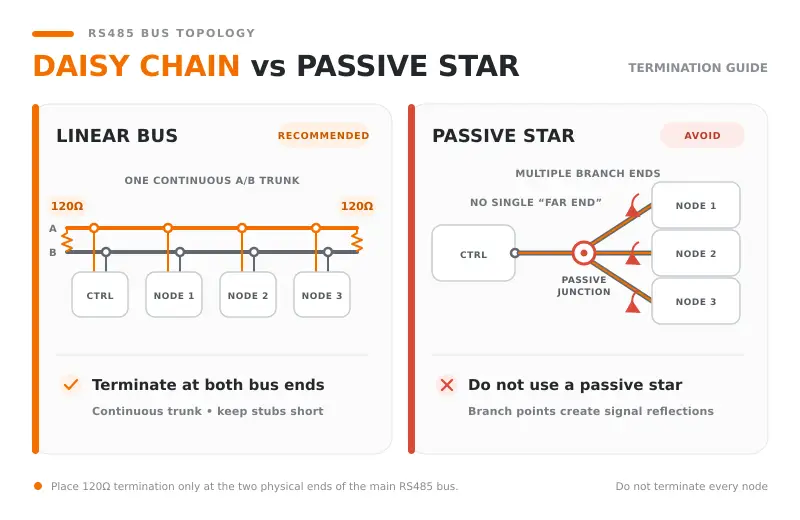
Run one main trunk from the first physical endpoint to the last, connecting intermediate devices along that route. This is often called daisy chaining. A device may have two cable entries, but electrically the pair should continue through the device with only a short connection to its transceiver.
A junction where several long passive branches leave one point is a star, even if installers call it a daisy chain. Each branch creates another discontinuity and reflection path. If the site genuinely requires long branches, use an active RS485 hub or isolated repeater so each branch becomes a separately managed segment.
Place Termination at the Two Physical Ends
Install termination across the data pair at the two physical ends of the trunk—not at every node and not merely at the logical master and last address. A common network uses a 120-ohm resistor at each end because that value matches many RS485 cables, but the actual component and switch settings must follow the cable and device documentation.
Some short, low-speed installations can operate without termination, and some devices include switchable or fixed termination internally. Inventory those features before adding resistors. With power removed, a bus containing two accessible 120-ohm end resistors will often measure close to 60 ohms across the pair, although connected electronics and other resistor networks can affect the reading.
Apply Biasing Once per Segment
Fail-safe bias resistors establish a known idle state when no driver is active. They are not the same as termination resistors. Enabling strong bias networks in every device can overload the bus, so identify whether the controller, converter, or transceivers already provide internal fail-safe behavior and follow the network design guidance.
For Modbus RTU, also verify that only one transmitter is active at a time, that silent intervals and serial settings are correct, and that every device uses the same baud rate, parity, and stop-bit configuration.
Separate Signal Reference, Shield, and Protective Earth
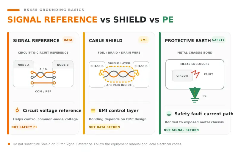
Differential signaling does not mean the receiver can tolerate an unlimited voltage difference between device grounds. A signal-reference conductor can help keep transceivers within their allowed common-mode range. The cable shield is for controlling electromagnetic interference, while protective earth is a safety connection. They are related at the system level but are not interchangeable conductors.
Whether a shield is bonded at one end or both ends depends on equipment design, equipotential bonding, frequency, cable construction, and site rules. Follow the manufacturers' grounding diagrams. If remote grounds can differ significantly, select galvanic isolation and appropriate surge protection instead of relying on a universal one-end-only rule.
6. How to Troubleshoot an RS485 Network
A Step-by-Step Diagnostic Workflow
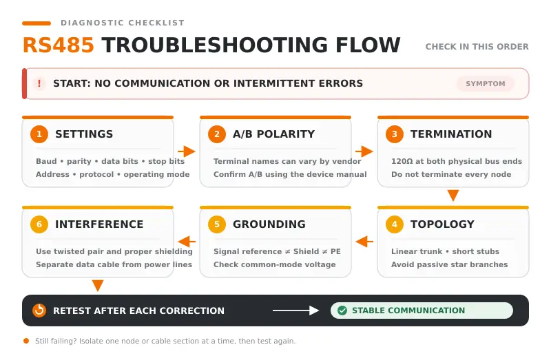
- Record the actual network. Draw the trunk, every branch, device, cable type, connector, terminator, bias source, shield bond, reference conductor, repeater, and power supply. Do not troubleshoot from an outdated drawing.
- Confirm the serial configuration. Match protocol, address, baud rate, parity, stop bits, timeout, and response delay. Check that no two slave devices use the same address.
- Verify polarity from manuals. A/B, D+/D-, and “inverting/non-inverting” labels are not applied consistently by all manufacturers. Compare terminal definitions, not letters alone.
- Inspect the physical route. Look for untwisted pair sections, long stubs, passive stars, damaged insulation, loose shields, poor crimping, weak screw-terminal contact, sharp bends, and parallel runs beside power cables.
- Check termination and bias. Power down where the equipment instructions require it. Confirm exactly two end terminations per segment and only the intended bias network.
- Simplify the network. Test one controller and one nearby device, then the far endpoint. Restore nodes one at a time until the fault returns.
- Measure the signal. Use an isolated or properly referenced oscilloscope and suitable probe technique to examine differential amplitude, ringing, reflections, noise, common-mode voltage, and driver turnaround at the failing location.
- Test under real conditions. Observe the bus while motors, drives, contactors, chargers, and other likely noise sources change state.
Scenario: It Works in the Lab but Fails On Site
A second field discussion involved a roughly 700-meter, 9,600-baud Modbus network with ten intended slave devices. A smaller setup worked in the office but failed after installation. The discussion exposed several common risks: termination enabled at too many nodes, biasing repeated across devices, polarity uncertainty, long field wiring, and possible ground-potential or noise problems.
The efficient response is not to replace random components. Start with two endpoints, validate one segment, add correct end termination, identify the single bias source, verify the reference and isolation plan, and then add one node at a time. If the required topology or distance exceeds a stable segment, divide it with isolated repeaters.
Symptom-to-Cause Troubleshooting Table
| Symptom | Likely Checks | First Corrective Action |
|---|---|---|
| No device responds | Wrong port mode, polarity, baud/parity, transmit control, or missing reference | Test two nearby devices with verified settings and pinouts |
| Nearby nodes work; distant nodes fail | Missing end termination, excessive length, cable loss, star branches, voltage drop | Validate trunk ends, cable type, stub lengths, and far-end waveform |
| Errors start when a motor runs | Cable routing, shield bonding, common-mode voltage, surge coupling | Separate routes and verify the EMC, grounding, and isolation design |
| Adding one node breaks the bus | Duplicate address, extra termination/bias, wiring fault, excessive loading | Disconnect that node and verify its settings and resistance before reconnecting |
| Intermittent CRC or framing errors | Reflections, noise, marginal common-mode range, timing, loose terminals | Correlate errors with waveform, equipment state, and physical movement |
Common RS485 Wiring Mistakes to Avoid
- Using a passive star while describing it as a daisy chain.
- Installing a termination resistor at every device.
- Enabling bias resistors in several devices without calculating the combined load.
- Running A and B on conductors from different twisted pairs.
- Leaving long untwisted sections at terminal blocks.
- Assuming A/B labels or RJ45/DB9 pinouts are universal.
- Using the shield as the normal signal reference or protective-earth conductor.
- Routing communications beside VFD output or high-current switching cables.
- Choosing cable solely by gauge while ignoring impedance, capacitance, jacket, and topology.
- Increasing software retries until an electrical-layer fault appears to disappear.
7. RS485 Cable FAQ and Final Selection Checklist
Can I Use Cat5 or Cat6 Cable for RS485?
Cat5 or Cat6 cable can work in some RS485 installations, especially over modest distances and when the equipment manufacturer permits it. However, Ethernet category cable is normally designed around 100-ohm differential impedance rather than the nominal 120 ohms common in RS485 systems. Connector mechanics, conductor type, shielding, environment, termination value, and the unused pairs also need consideration. For a critical or long industrial run, a purpose-specified RS485 cable is the safer baseline.
Does RS485 Need a Ground Wire or Shield?
RS485 uses differential signaling, but every transceiver still has an allowed common-mode range. A signal-reference conductor may be needed to keep remote devices within that range. A shield may be appropriate for noise control, but its bonding method is a separate EMC decision. Follow the device manufacturer; use isolation where large ground differences or surge exposure are possible.
Is Modbus Cable the Same as RS485 Cable, and How Far Can It Run?
Modbus RTU is a messaging protocol, while RS485 is an electrical interface. A cable sold for Modbus RS485 normally means its construction is suitable for that physical layer and installation. There is no single guaranteed maximum length: reach decreases as data rate, capacitance, node loading, stub length, noise, and installation losses increase. About 1,200 meters is frequently cited as an upper-order reference for low-speed, well-designed RS485 links, not as a promise for every system. Use the transceiver, protocol, and cable manufacturers' limits, and segment the network when necessary.
Final RS485 Cable Selection Checklist
- Confirm whether the interface is 2-wire or 4-wire and whether the converter supports it.
- Verify protocol, baud rate, parity, stop bits, addresses, response timing, and required length.
- Select a twisted pair with appropriate nominal impedance, capacitance, gauge, and strand type.
- Choose shielding and a jacket for the actual noise, temperature, moisture, oil, UV, flex, and code conditions.
- Design one linear trunk with short stubs, or use active hubs/repeaters for required branches.
- Locate the two physical ends and document termination and bias settings before commissioning.
- Confirm A/B definitions, every connector pinout, and the signal-reference connection from device manuals.
- Plan shield bonding, protective earth, isolation, and surge protection at the system level.
- Record baseline resistance, waveforms, and error counts so future maintenance has a known-good reference.
A reliable RS485 network is a complete transmission system, not just a cable purchase. When cable construction, topology, termination, reference, protection, and serial settings are designed together, the result is easier to commission and far less likely to become an intermittent field problem.
Related Guides
- RS232 vs RS485 vs RS422: Key Differences in Distance, Speed & Wiring
- What Is an RS232 Cable Used For? Applications, Types and Selection Guide
- Elecbee M12 connector technology
.jpg?x-oss-process=image/resize,w_600,h_600/quality,q_90/watermark,image_aW1hZ2UvcGFuZGEucG5n,P_50,t_40,g_center,x_0,y_0/format,webp)