

 0
0
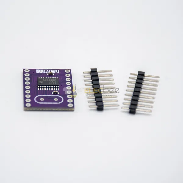
Choosing a 24-bit ADC module is not simply a matter of buying the converter with the highest sample rate or largest number of channels. The ADS1256, ADS1232, and ADS1220 are all precision delta-sigma converters, but they are designed for different signals and system architectures.
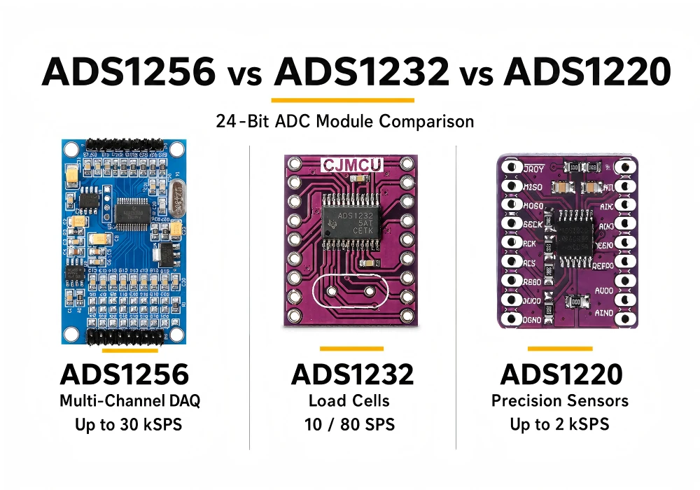
The ADS1256 is a strong choice for multi-channel precision data acquisition. The ADS1232 is optimized for load cells and resistive bridge sensors. The ADS1220 combines low power with a programmable gain amplifier, voltage reference, and excitation-current sources for temperature and bridge measurements.
This guide compares these converters, explains the ADS1232 pinout and ADS1256 wiring, and shows how to avoid the noise, input-range, and calibration mistakes that prevent a nominal 24-bit ADC from delivering useful precision.
Quick Answer: Choose ADS1232 for load cells and electronic scales, ADS1220 for low-power temperature or bridge sensors, and ADS1256 for higher-rate, multi-channel precision acquisition. Choose by signal requirements—not bit count alone.
1. ADS1256, ADS1232, or ADS1220: Which ADC Should You Choose?
Quick Selection Recommendations
- Choose ADS1256 when you need up to eight single-ended or four differential inputs and data rates up to 30 kSPS.
- Choose ADS1232 for a load cell, strain gauge, weigh scale, or bridge pressure sensor operating at 10 or 80 SPS.
- Choose ADS1220 for RTDs, thermocouples, thermistors, and bridge sensors requiring up to 2 kSPS.
- Choose ADS1115 when I2C convenience and slow 16-bit measurements matter more than maximum speed.
- Choose ADS1118 when you need a 16-bit SPI ADC with an integrated temperature sensor.
- Choose ADS1292R only for ECG, respiration impedance, or related biopotential applications—not as a generic sensor ADC.
When a Microcontroller ADC Is Good Enough
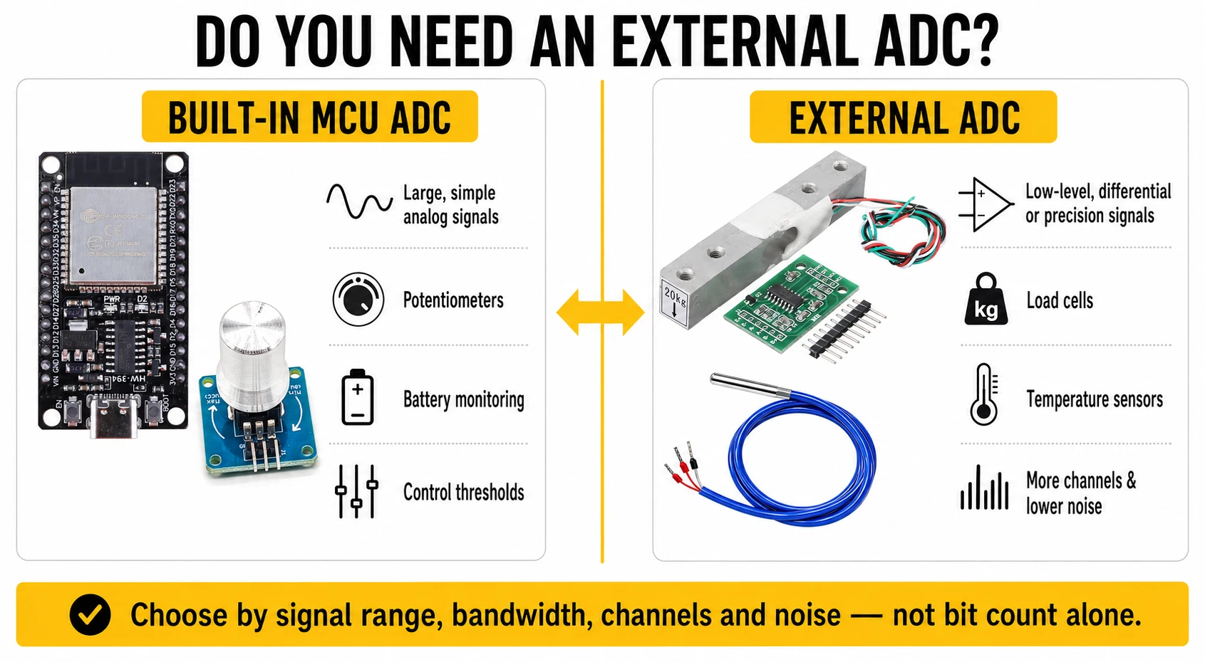
An Arduino, ESP32, or STM32 internal ADC may be sufficient for potentiometers, control thresholds, battery monitoring, joysticks, and sensors producing relatively large voltage changes.
Before adding an external module, connect a stable voltage source to the MCU ADC and record several thousand readings. If the noise, linearity, channel count, and sample rate already meet the requirement, an external converter may add unnecessary cost and complexity.
STM32 controllers can also use timers and DMA to transfer ADC samples directly into memory with little CPU intervention. This makes an internal ADC practical for many medium-speed acquisition systems.
When You Need an External ADC Module
An external ADC becomes useful when the project needs differential inputs, programmable gain, a precision voltage reference, additional channels, better low-frequency noise performance, or separation from a noisy wireless microcontroller.
ESP32 remains an excellent wireless controller, but its internal ADC may require calibration, input bypass capacitance, and multisampling. For low-level pressure, weight, or temperature sensors, using an external converter can be simpler than trying to correct every limitation in firmware.
2. How to Evaluate a 24-Bit ADC Module
Resolution vs. Real-World Accuracy
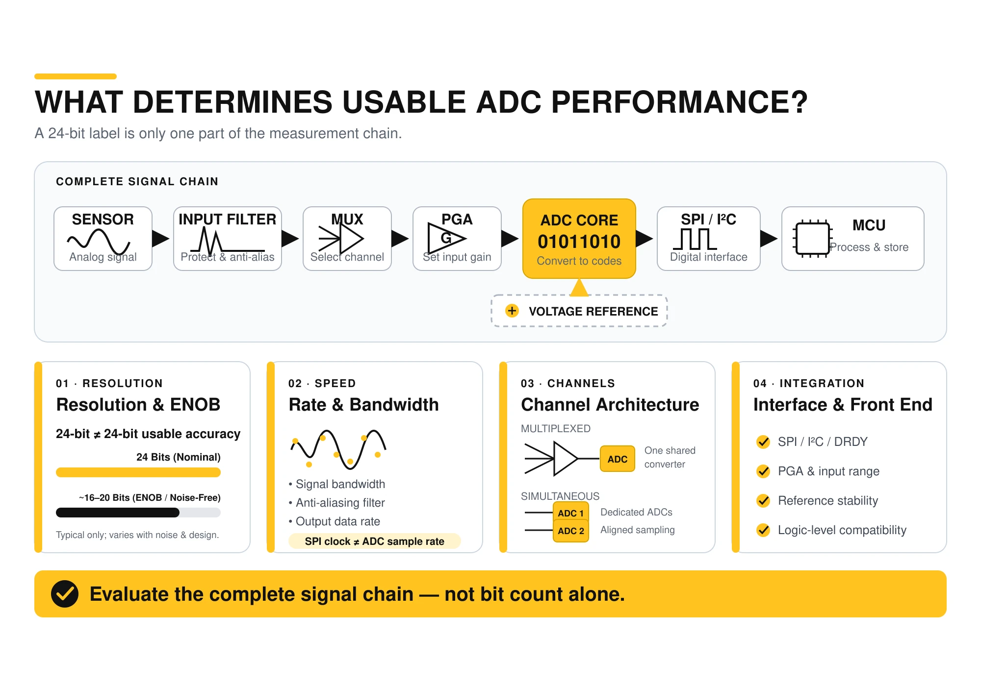
A 24-bit ADC produces up to 16,777,216 digital codes. It does not guarantee 24 bits of noise-free measurement. Effective number of bits, input-referred noise, offset, gain error, nonlinearity, reference stability, and temperature drift determine how much information is actually usable.
A properly designed 16-bit measurement system can outperform a 24-bit breakout board powered from a noisy rail. Compare the complete signal chain rather than the advertised resolution alone.
Sample Rate and Signal Bandwidth
Define the signal bandwidth before selecting an ADC. Static weight and temperature measurements are slow and can benefit from low output data rates and stronger digital filtering. Vibration, audio, power-waveform analysis, and pulse capture require substantially more bandwidth.
The theoretical sampling minimum is twice the highest signal frequency, but practical systems require an anti-aliasing filter and additional margin. Also distinguish the ADC output data rate from the SPI clock rate. A fast SPI bus cannot force the ADC to generate conversions faster.
Channels, Multiplexing, and Simultaneous Sampling
The ADS1256 has eight analog inputs, but it contains a multiplexed converter. It does not sample eight channels simultaneously at 30 kSPS per channel. The channels share the conversion capacity, and switching inputs introduces configuration and settling overhead.
If phase alignment between channels matters, choose an ADC with separate simultaneous converters. ADS1292R, for example, contains two simultaneous ADC channels because ECG applications require a different architecture from a general-purpose multiplexed data-acquisition board.
SPI, I2C, Reference, and PGA
I2C uses fewer pins and is convenient for slow sensor systems. SPI generally provides higher throughput and more predictable timing. ADS1256 and ADS1220 use SPI-compatible interfaces. ADS1232 uses a simpler clock-and-data serial output consisting primarily of DRDY/DOUT and SCLK.
Do not select a module until you have verified its analog supply, digital logic voltage, reference source, PGA ranges, input common-mode limits, and surrounding PCB components.
3. ADS1256 vs. ADS1232 vs. ADS1220 Comparison
ADC Module Comparison Table
| Converter | Resolution | Maximum Rate | Channels | Interface | Recommended Use |
|---|---|---|---|---|---|
| ADS1256 | 24-bit | 30 kSPS | 8 single-ended or 4 differential | SPI | Multi-channel precision data acquisition |
| ADS1232 | 24-bit | 10 or 80 SPS | 2 differential | Two-wire serial | Load cells, scales, and bridge sensors |
| ADS1220 | 24-bit | 2 kSPS | 4 single-ended or 2 differential | SPI | RTDs, thermocouples, and low-power sensors |
| ADS1115 | 16-bit | 860 SPS | 4 single-ended or 2 differential | I2C | Slow general-purpose sensor measurements |
| ADS1118 | 16-bit | 860 SPS | 4 single-ended or 2 differential | SPI | Thermocouples and temperature-aware systems |
| ADS1292R | 24-bit | 8 kSPS | 2 simultaneous channels | SPI | ECG and respiration research prototypes |
Best Module by Application
For an electronic scale, ADS1232 is generally the most direct solution. For a thermocouple, RTD, or low-power industrial sensor, ADS1220 provides more integrated sensor features. For a system collecting several precision voltage channels at higher rates, ADS1256 is the stronger candidate.
General-Purpose 16-Bit I2C ADC Options
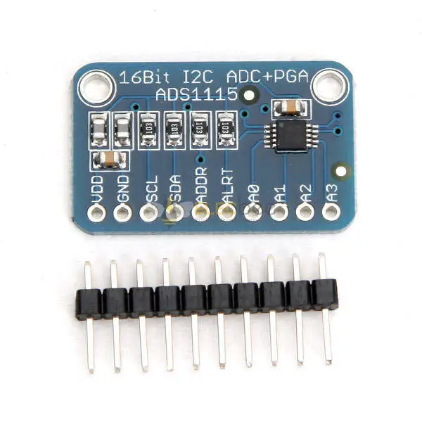
ADS1115 is a practical choice when a microcontroller needs additional analog inputs, programmable gain, and a simple two-wire interface.
View ADS1115 Module View CJMCU-ADS1115 View 5pcs ADS1115 Set
16-Bit SPI ADC for Temperature Measurement
ADS1118 combines 16-bit conversion, SPI communication, programmable gain, an internal reference, and an internal temperature sensor.
Low-Power 24-Bit Precision Sensor ADC
ADS1220 integrates a PGA, reference, oscillator, temperature sensor, and programmable current sources for RTDs, thermocouples, thermistors, and bridge sensors.
Where ADS1292R Fits
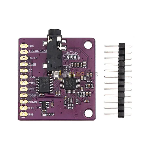
ADS1292R should be treated as a biosensing analog front end. Its simultaneous channels, right-leg-drive amplifier, lead-off detection, and respiration-impedance circuitry add value for ECG research but unnecessary complexity for ordinary voltage or load-cell measurements.
The module is intended for evaluation, education, and prototype development. The finished-system designer remains responsible for isolation, electrical safety, validation, and applicable regulatory requirements.
4. ADS1232 Pinout and Load Cell Wiring
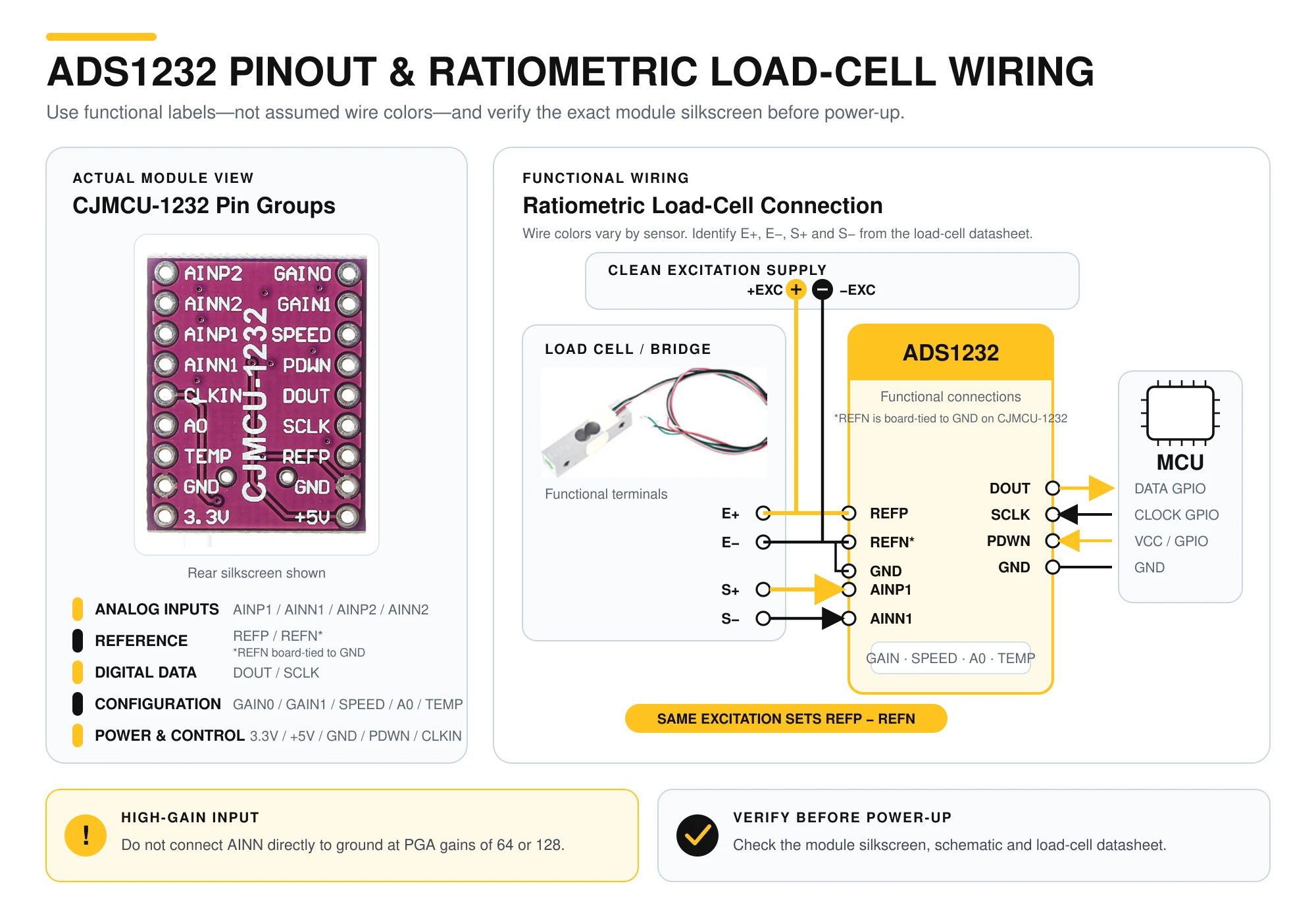
ADS1232 Pin Function Groups
The ADS1232 pinout can be understood in five functional groups. Module header order varies, so always compare the board silkscreen and schematic with the chip documentation.
| Group | Signals | Purpose |
|---|---|---|
| Analog Inputs | AINP1, AINN1, AINP2, AINN2 | Two differential sensor channels |
| Reference | REFP, REFN | Defines the conversion reference |
| Digital Data | DRDY/DOUT, SCLK | Data-ready indication and serial transfer |
| Configuration | GAIN0, GAIN1, SPEED, A0, TEMP | Selects gain, data rate, channel, or temperature sensor |
| Power and Control | AVDD, DVDD, AGND, DGND, PDWN, clock pins | Power, shutdown, and clocking |
How to Connect a Load Cell
- Connect the bridge excitation-positive and excitation-negative wires to a clean excitation supply.
- Use the same excitation voltage as the ADC reference when possible. This ratiometric arrangement reduces errors caused by excitation drift.
- Connect the load-cell signal-positive wire to AINP1 and signal-negative wire to AINN1.
- Connect DRDY/DOUT and SCLK to two MCU GPIO pins.
- Set the gain pins for the expected differential signal range.
- Start at 10 SPS for lower noise and 50/60 Hz rejection.
- Perform offset calibration with no applied load before calculating weight.
Gain, Speed, Channel, and Calibration Pins
GAIN1 and GAIN0 select gains of 1, 2, 64, or 128. SPEED selects 10 or 80 SPS. A0 selects between the two differential input pairs, while TEMP can route the internal temperature sensor to the ADC.
ADS1232 has no conventional configuration registers. Its major operating modes are controlled by pins. Offset calibration is initiated using the additional clock pulses defined by the device timing requirements.
ADS1232 Wiring Mistakes
At gains of 64 or 128, do not assume the negative analog input can be connected directly to ground. The amplifier has a restricted common-mode range. Both bridge outputs normally sit near the midpoint of the excitation supply, which is appropriate for differential measurement.
Other common mistakes include using separate unstable reference and excitation supplies, leaving configuration pins floating, routing digital clocks beside the bridge input, and expecting averaging to correct an overloaded PGA.
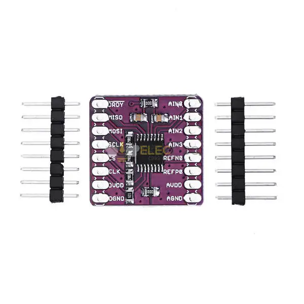
Choose an ADS1232 board for load cells, strain gauges, pressure sensors, and weighing projects:
5. How to Connect and Test an ADS1256 ADC Module
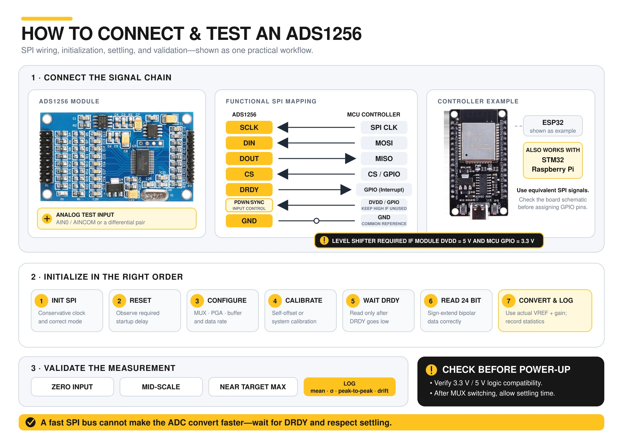
ADS1256 SPI Wiring
- SCLK: SPI clock from the controller.
- DIN: SPI data from the controller to the ADC.
- DOUT: Conversion data from the ADC.
- CS: Chip-select signal.
- DRDY: Active-low conversion-ready indication.
- PDWN/SYNC: Power-down and synchronization control.
- AIN0–AIN7: Eight single-ended or four differential inputs.
Check the exact breakout-board schematic before connecting it to a 3.3 V ESP32, STM32, or Raspberry Pi. A module powered from 5 V is not automatically compatible with 3.3 V GPIO.
Recommended Initialization Sequence
- Initialize SPI at a conservative clock rate and the correct communication mode.
- Reset the converter and observe its required startup delay.
- Configure the input multiplexer, buffer, PGA, and output data rate.
- Run self-offset or system calibration.
- Wait for DRDY before reading each 24-bit result.
- Sign-extend bipolar conversion data correctly.
- Convert raw codes using the actual reference voltage and selected gain.
Channel Switching and Settling
The 30 kSPS specification is the maximum converter data rate, not the sustained rate for every channel simultaneously. After changing the multiplexer, allow the digital filter and analog signal path to settle before accepting the measurement.
High source impedance can increase settling time. If a sensor or resistor divider cannot drive the input properly, use an appropriate buffer or reduce the required channel-switching speed.
Calibration and Validation
Test zero, mid-scale, and a point near the maximum intended signal. Record the mean, standard deviation, peak-to-peak spread, and drift over time. Repeat the test with Wi-Fi, displays, relays, and switching regulators enabled.
Use a stable battery or precision voltage source to separate ADC problems from sensor and amplifier problems. Calibration can correct offset and gain, but it cannot remove random noise or unstable reference voltage.
View ADS1256 8-Channel ADC Module
6. Noise Reduction and Real-World Application Examples
How to Reduce ADC Noise
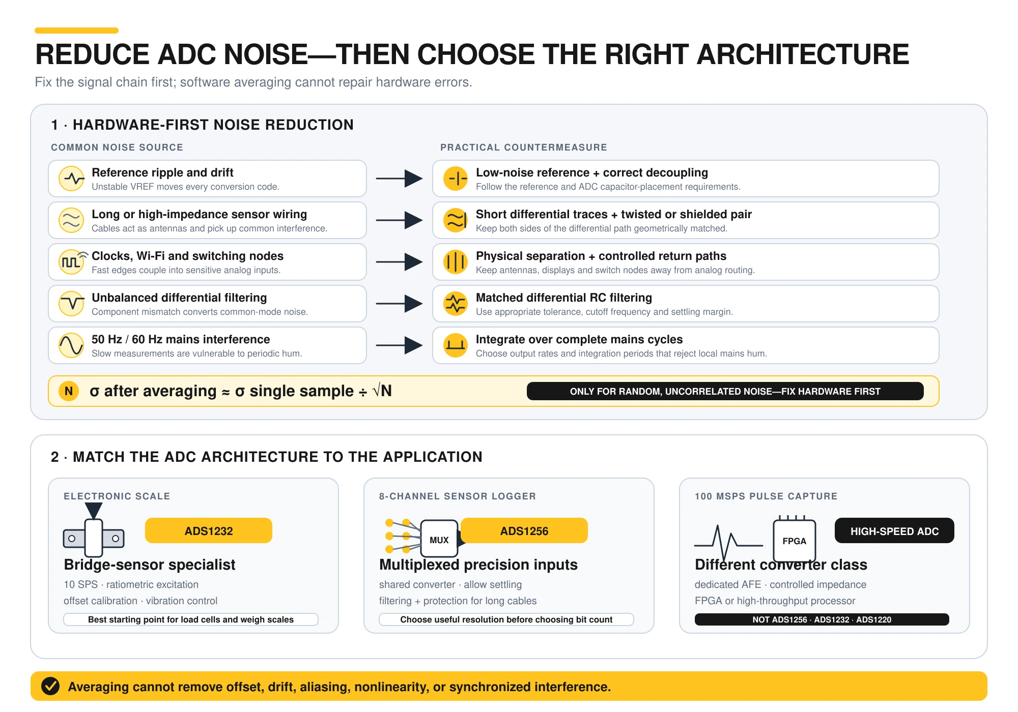
- Use a low-noise reference and follow its decoupling requirements.
- Keep differential and high-impedance analog traces short.
- Keep clocks, antennas, switching nodes, and display signals away from analog inputs.
- Use matched differential filtering where appropriate.
- Route remote sensors with twisted-pair or shielded cable.
- Average samples only after correcting hardware problems.
- Integrate over complete 50 Hz or 60 Hz mains cycles when measuring slow signals.
Averaging N uncorrelated samples reduces random-noise standard deviation by approximately the square root of N. It does not remove offset, drift, nonlinearity, aliasing, or synchronized interference.
Electronic Scale and Load Cell Example
A load cell produces a small differential voltage. ADS1232 is usually a better starting point than a generic MCU ADC combined with a high-gain general-purpose op-amp because it integrates a low-noise PGA and filtering intended for bridge sensors.
Use ratiometric excitation, begin at 10 SPS, perform unloaded offset calibration, and characterize mechanical vibration. Airflow, cable movement, nearby traffic, and building vibration can appear as genuine load-cell signals rather than electronic noise.
Eight-Channel ESP32 Sensor Logger
For four temperature and four pressure sensors, first determine whether 12, 16, or 24 useful bits are required. ADS1256 provides eight multiplexed inputs and higher precision, while a faster 12-bit eight-channel converter may be more appropriate if throughput matters more than small-signal resolution.
Long automotive sensor cables also require filtering, input protection, correct grounding, and transient suppression. Installing a 24-bit ADC does not protect an input from load dump, ESD, or ground-potential differences.
Why 100 MSPS Projects Need a Different ADC
ADS1256, ADS1232, and ADS1220 cannot capture nanosecond pulses or provide oscilloscope-class sampling. A 100 MSPS project requires a dedicated high-speed ADC, a suitable analog front end, controlled-impedance PCB design, and often an FPGA or high-throughput processor.
7. ADC Module FAQ and Final Selection Checklist
Frequently Asked Questions
Is ADS1220 an I2C ADC?
No. ADS1220 uses an SPI-compatible interface. Product listings that describe it as I2C should be verified against the chip specifications before wiring.
Does a 24-bit ADC provide 24-bit accuracy?
No. Nominal resolution describes the number of output codes. ENOB, noise-free resolution, reference stability, offset, nonlinearity, and the analog front end determine usable accuracy.
ADS1256 vs. ADS1232: Which Is Better for a Load Cell?
ADS1232 is normally the better fit for a slow load-cell or scale because it is designed for bridge sensors. ADS1256 is more appropriate when additional channels or higher data rates are required.
ADS1256 vs. ADS1220: Which Is Faster?
ADS1256 supports data rates up to 30 kSPS, while ADS1220 supports up to 2 kSPS. ADS1220 provides integrated functions aimed at low-power temperature and bridge-sensor measurement.
Can ADS1256 Sample Eight Channels at 30 kSPS Each?
No. Its inputs share a multiplexed converter. Channel switching and filter settling reduce the sustained rate available to each channel.
Is ADS1292R a General-Purpose ADC?
It can digitize analog signals, but it is specifically designed as an ECG and respiration-impedance analog front end. Its feature set is not optimized for ordinary voltage, temperature, or load-cell projects.
ADC Module Buying Checklist
- Required signal bandwidth and output data rate
- Smallest voltage change that must be detected
- Actual ENOB and noise-free resolution
- Single-ended, differential, or simultaneous channels
- Input common-mode and absolute-voltage limits
- PGA range and source-impedance requirements
- Reference accuracy and temperature drift
- SPI, I2C, or two-wire serial interface
- Module and MCU logic-level compatibility
- Multiplexer and digital-filter settling time
- Schematic, documentation, and component traceability
- Calibration and environmental-test requirements
Final Recommendations
Choose ADS1232 for load cells and electronic scales, ADS1220 for low-power precision temperature and bridge sensors, and ADS1256 for multi-channel precision data acquisition. Use ADS1115 for convenient low-speed I2C measurements and ADS1118 when a similar 16-bit converter with SPI is preferred.
Do not choose by resolution alone. Start with the signal bandwidth, input range, channel architecture, reference, and noise target. A correctly designed 16-bit measurement chain can outperform a poorly powered or badly laid-out 24-bit module.
Continue Exploring Embedded Measurement Systems
Click here to read the next article: STM32 vs ESP32: Which Microcontroller Should You Choose for IoT Projects?
Continue exploring microcontroller selection, analog sensing, wireless connectivity, and data-acquisition design. Stay tuned.