0
0
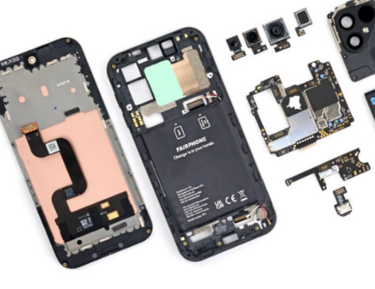
Modern electronics are becoming thinner, lighter and more compact every year. Smartphones fold in half, laptops use ultra-thin display assemblies, and even industrial equipment now relies on compact flexible interconnect systems.
This is why FFC and FPC cables have become so common.
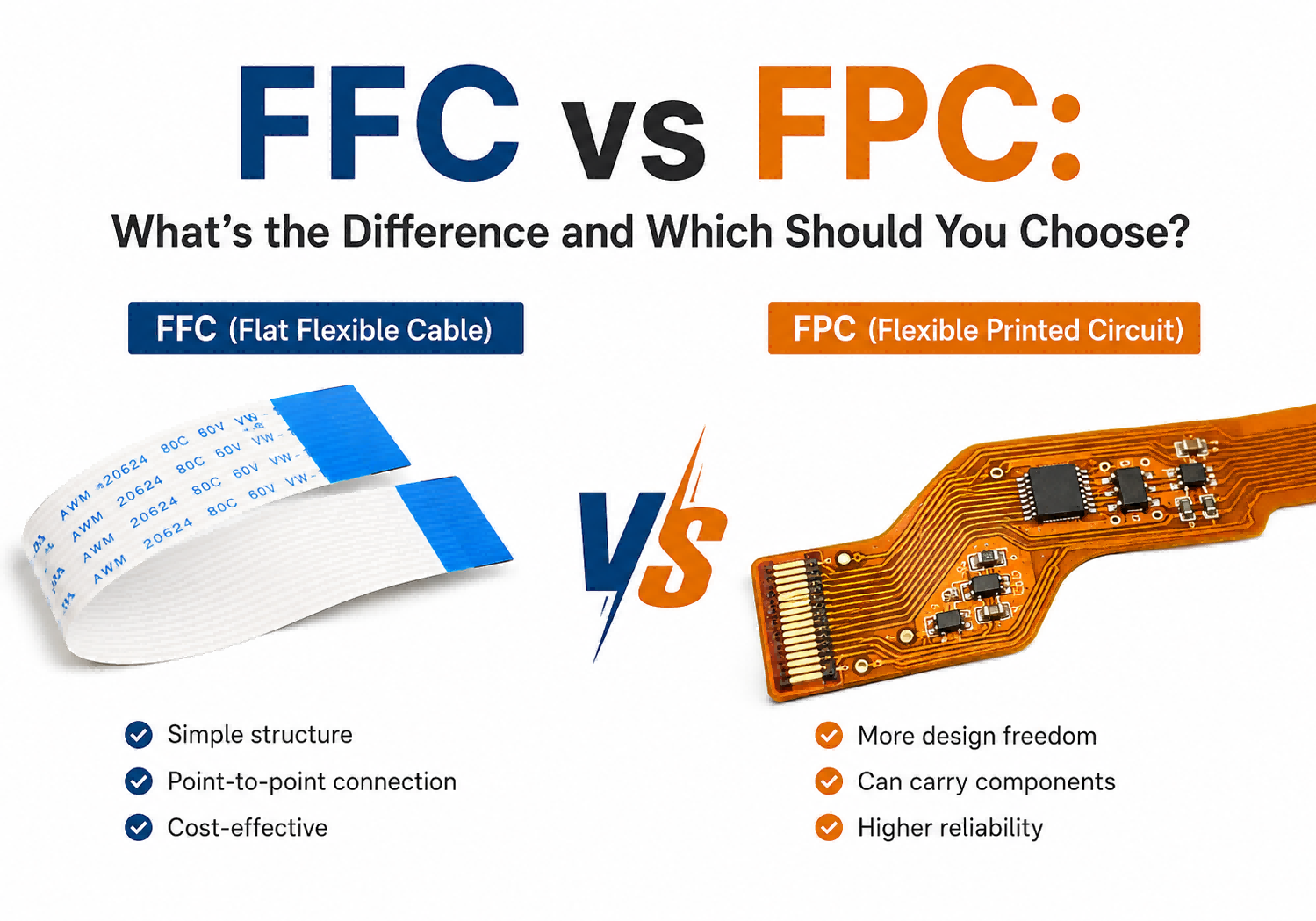
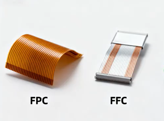
At first glance, they look very similar. Both are flat, flexible and often called “ribbon cables” online. However, FFC and FPC are fundamentally different technologies.
An FFC is primarily a flexible interconnect cable.
An FPC is essentially a flexible PCB.
That difference affects:
- Signal integrity
- Repair difficulty
- Reliability
- Manufacturing cost
- Dynamic flex performance
- Connector design
This guide explains the real-world engineering differences between FFC and FPC cables, including practical repair issues, common failure modes and why modern smartphones increasingly prefer FPC structures.
1. What Are FFC and FPC Cables?
What Does FFC Mean?
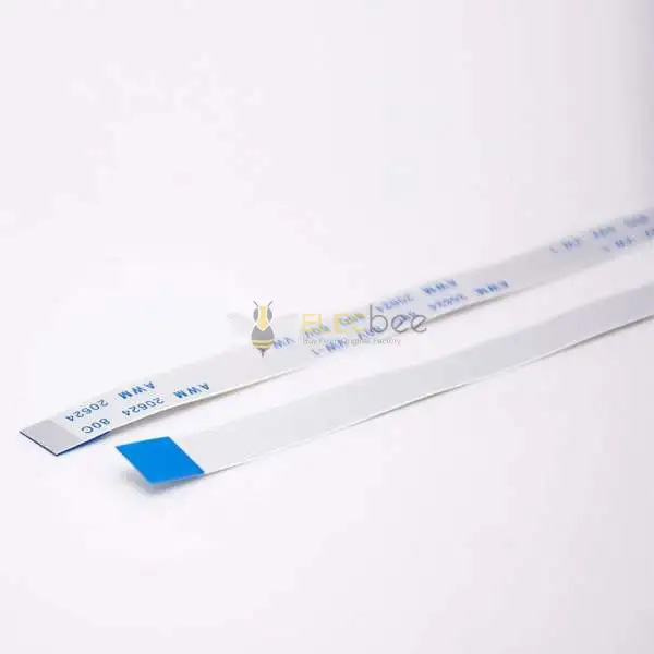
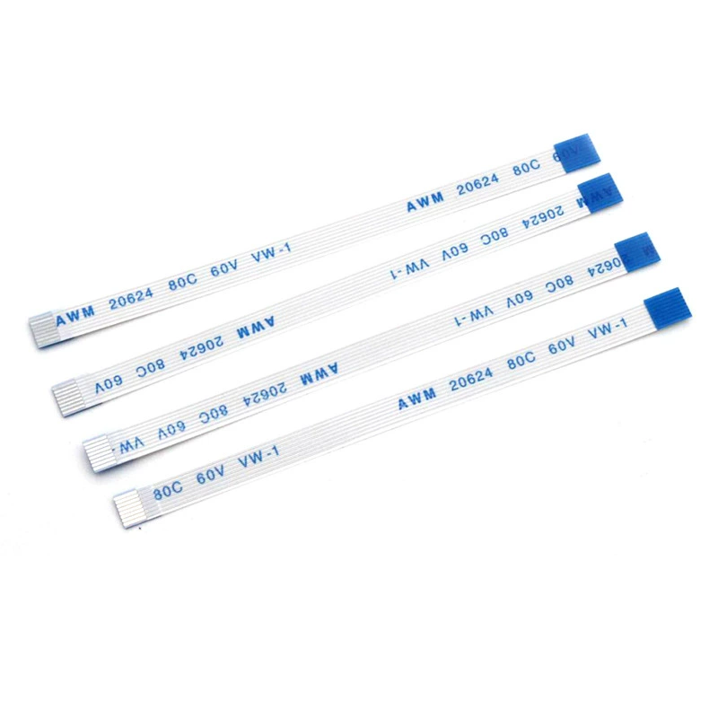
FFC stands for Flexible Flat Cable.
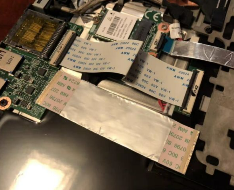
An FFC cable usually consists of flat parallel copper conductors laminated between thin PET insulation layers.
FFC cables are primarily designed for simple point-to-point electrical connections.
Because they are inexpensive and easy to manufacture, they are widely used in:
- Printers
- TVs
- DVD drives
- Scanners
- Laptops
- Gaming consoles
Modern electronics increasingly use FFC and FPC systems to replace traditional round wires or older IDC ribbon cables in order to:
- Save space
- Reduce thickness
- Simplify routing
- Improve assembly efficiency

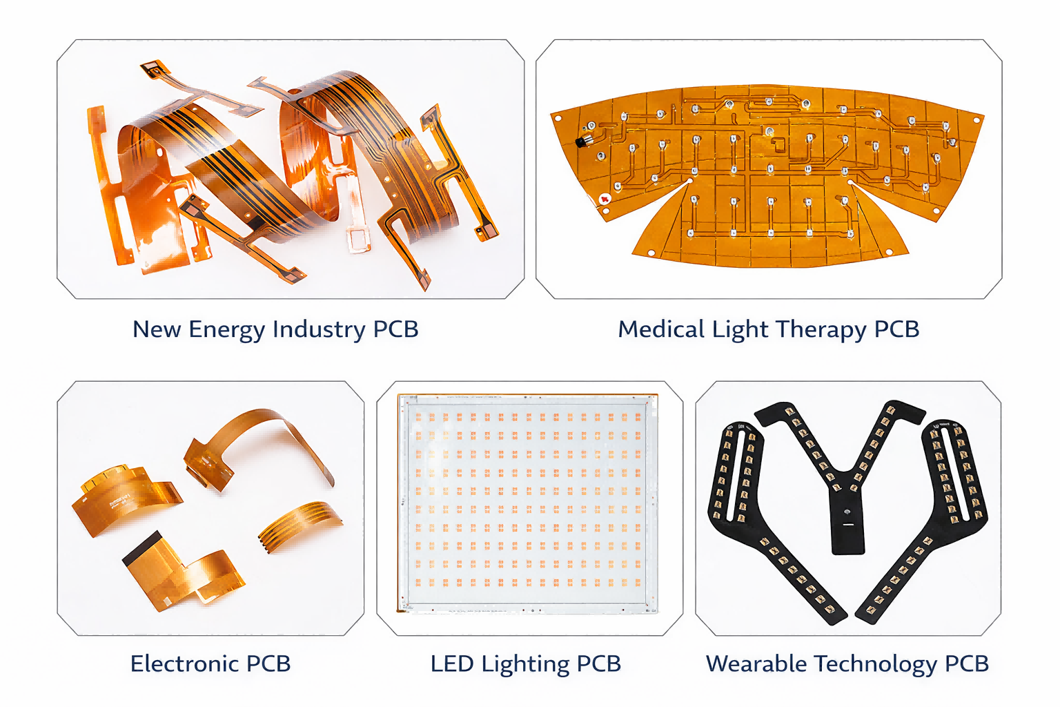
What Does FPC Mean?
FPC stands for Flexible Printed Circuit.
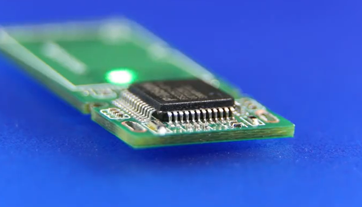
Unlike FFC cables, FPCs are actual printed circuits built on flexible polyimide substrate material.
This is one of the most important conceptual differences between the two.
An FFC is mainly a cable.
An FPC behaves much more like a flexible PCB.
FPCs can include:
- Etched copper traces
- Ground planes
- Controlled impedance routing
- Shielding layers
- Multiple layers
- Fine-pitch signal routing
- Mounted electronic components
Some FPC assemblies even carry:
- Capacitors
- Resistors
- LEDs
- IC chips
This makes FPC far more capable for compact modern electronics.
Why People Often Confuse Them
Both FFC and FPC are flat and flexible.
Both commonly connect through:
- ZIF connectors
- Flip-lock connectors
- Fine-pitch board connectors
In repair communities, users often call both of them “ribbon cables” or “flex cables,” even though their internal structure is completely different.
2. Key Structural Differences
Laminated vs Etched Structure
The biggest structural difference is how they are manufactured.
FFC cables use laminated copper conductors sandwiched between plastic insulation layers.
FPCs use etched copper circuitry on flexible polyimide substrate material.
This gives FPCs far greater design freedom.
Unlike simple FFC cables, FPCs can support:
- Curved trace routing
- Dense interconnect layouts
- Ground reference planes
- High-speed differential routing
- Component mounting zones

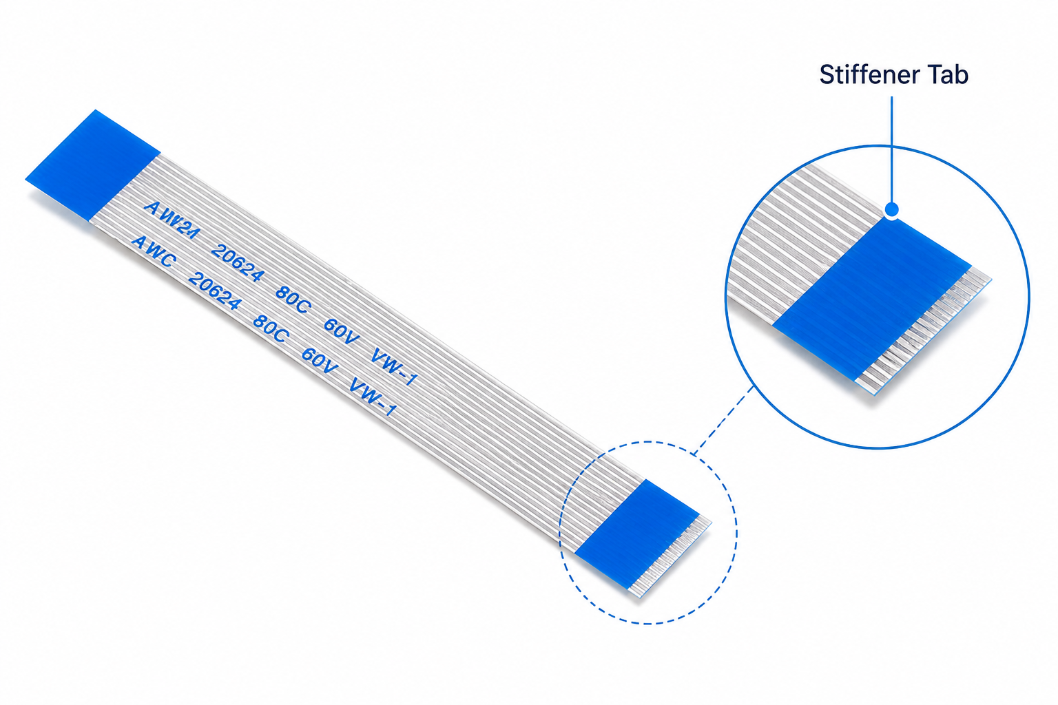
Stiffeners and Reinforcement Materials
FFC cables commonly use simple blue or transparent stiffener tabs near the connector area.
These reinforcement tabs help:
- Improve insertion rigidity
- Reduce connector stress
- Maintain thickness consistency
FPC reinforcement structures are usually much more advanced.
Depending on the application, FPC stiffeners may use:
- FR-4 fiberglass
- Polyimide (PI)
- Stainless steel
- Aluminum reinforcement
These materials help strengthen connector zones or support mounted components.
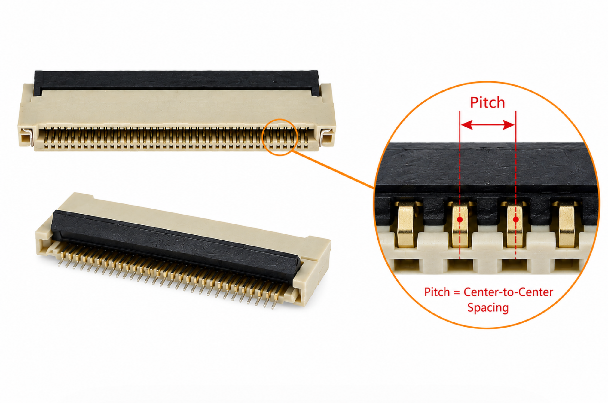
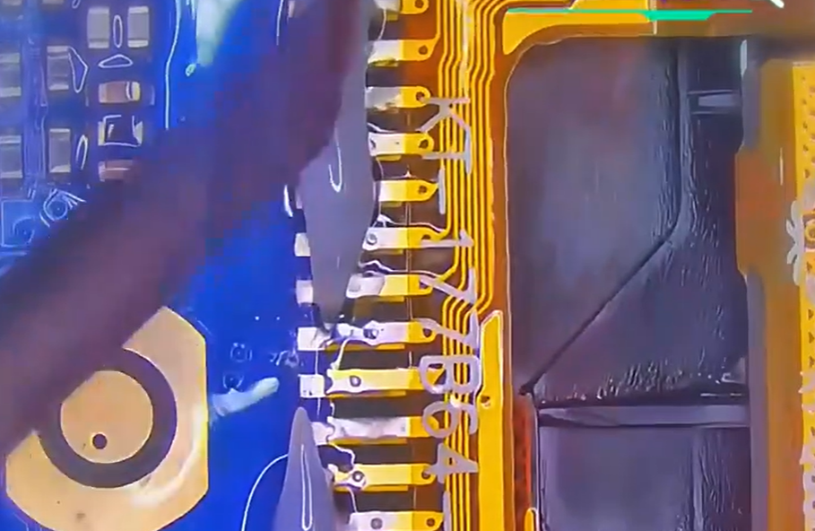
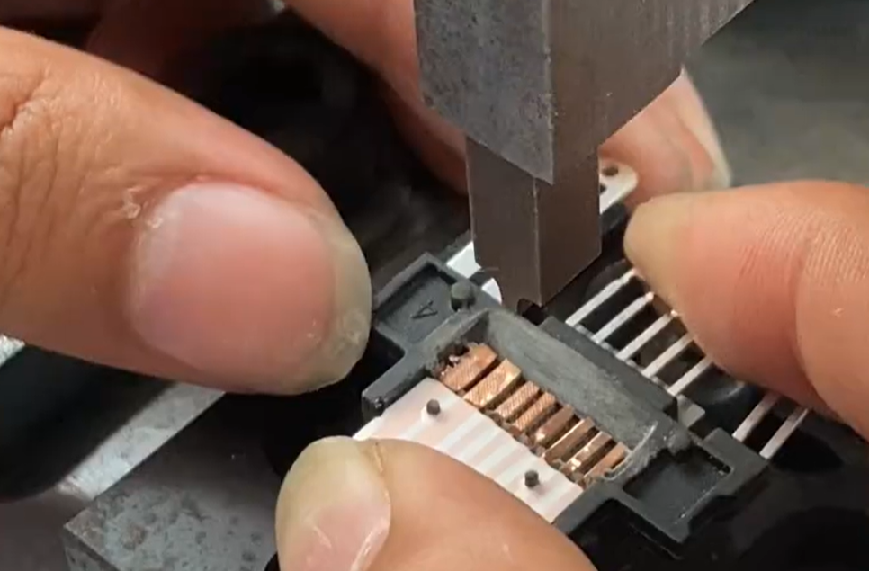
Connector Pitch and Size Differences
FPC connectors are often significantly finer pitch than standard FFC connectors.
Common pitches include:
As pitches shrink down to 0.2 mm in modern smartphones and OLED display assemblies, the margin for error during repair becomes virtually zero.
At these sizes:
- Alignment becomes extremely difficult
- Bridging becomes common
- Plastic deformation risk increases
- Connector damage becomes very easy
This is one reason smartphone FPC repair is considered advanced microsoldering work.
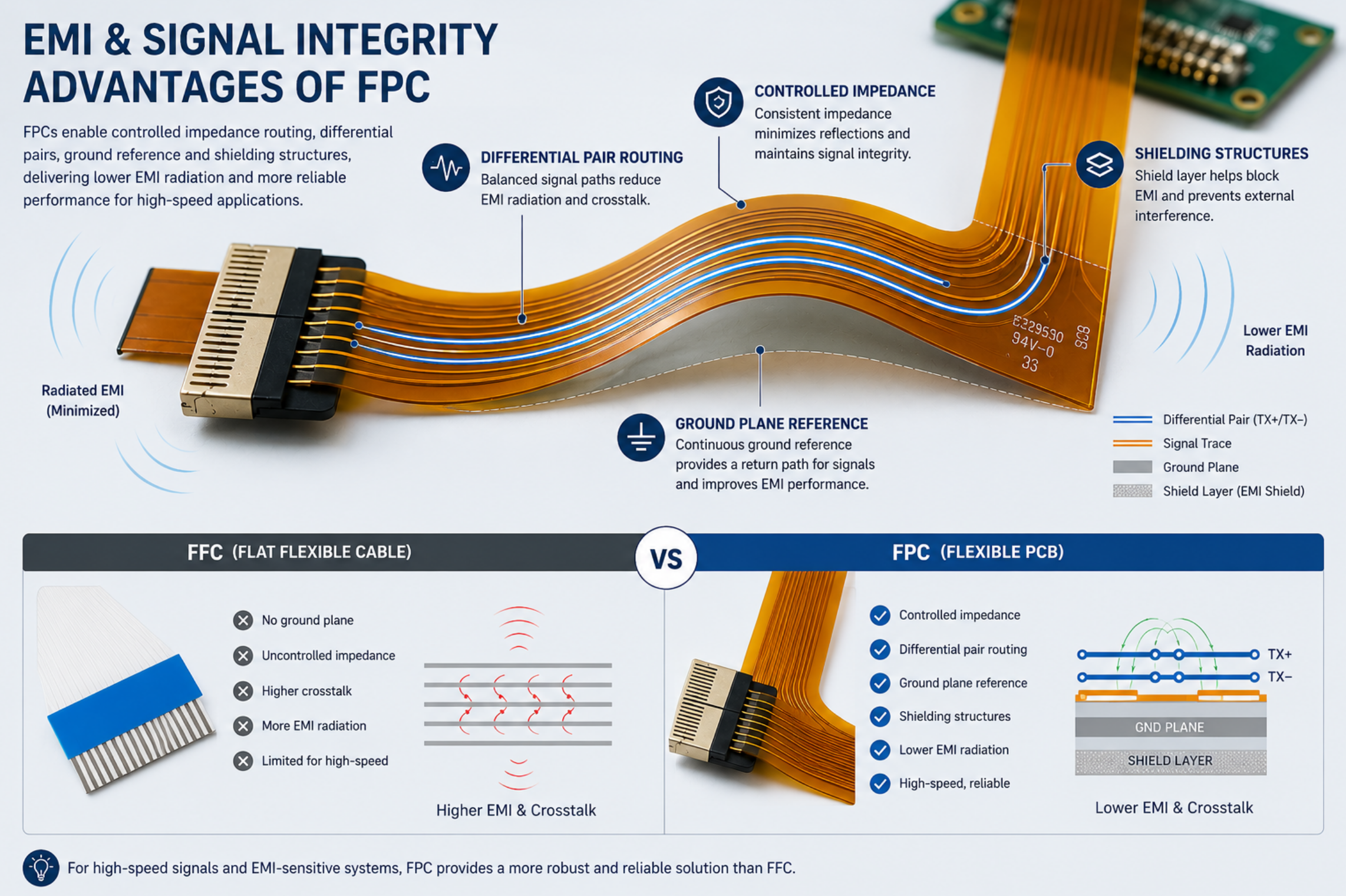
EMI and Signal Integrity Considerations
FPC is usually the better choice for high-speed signals.
Because FPCs can include:
- Controlled impedance routing
- Differential pair layouts
- Ground planes
- Shielding structures
They generally provide better EMI performance than simple FFC cables.
In one engineering discussion about Ethernet PHY routing, engineers noted that FFC cables may work for short low-speed applications, but FPC designs are safer for signal integrity-sensitive systems.
3. Why Are FPC Connectors So Fragile?
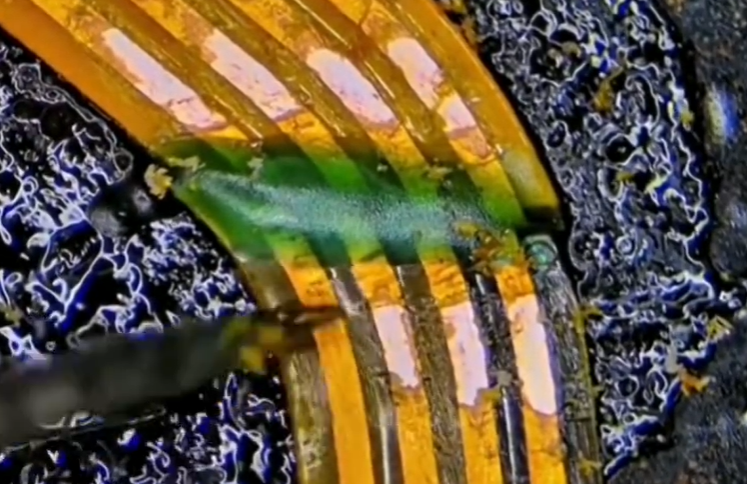
Heat Damage During Repair
One of the most common complaints about FPC connectors is how easily they melt during repair.
Repair technicians often describe FPC replacement as frustrating because:
- Too much heat melts the connector
- Too little heat prevents removal
- Nearby components are extremely small
- Plastic warps very easily
One technician described the experience perfectly:
“Either they don’t budge or they melt.”
This is especially common during smartphone motherboard repair.
Broken Latches and Connector Wear
Another major issue is connector latch damage.
Common failures include:
- Broken flip-lock tabs
- Cracked retaining clips
- Bent contacts
- Worn insertion surfaces
Once the latch fails, intermittent charging or audio problems can appear even if the cable itself is still functional.
Why Smartphone FPC Repairs Are Difficult
Modern smartphone FPC repair combines multiple difficult challenges:
- Ultra-fine pitch connectors
- Tiny nearby SMD components
- Heat-sensitive plastics
- Dense motherboard layouts
- Very limited working space
Many hobbyists eventually decide to send their phones to professional microsoldering shops after struggling with alignment and hot-air rework.
Professional Repair Techniques
Experienced technicians often recommend:
- Large hot-air nozzles
- Bottom heating
- Low-temperature solder
- Fine-tip soldering irons
- Microscope inspection
- High-quality flux
Many technicians also use Kapton tape or metal heat shields to protect nearby plastic components during hot-air rework.
4. Common FFC Cable Failure Problems
Torn Ribbon Cable Traces
FFC ribbon cables commonly fail because of:
- Sharp bending
- Repeated movement
- Connector stress
- Accidental pulling
Repair technicians sometimes repair torn FFC traces by:
- Scraping insulation to expose copper
- Bridging traces with ultra-thin wire
- Reinforcing the repair with Kapton tape
- Using conductive silver paint
Delaminated Blue Stiffener Tabs
Retro console repair communities frequently complain about aging FFC stiffener tabs.
Older systems such as the PS2 often suffer from:
- Weak adhesive bonding
- Detached blue tabs
- Oxidized contacts
- Brittle cable material
Modern replacement cables usually bond the stiffener more securely using heat-press manufacturing methods.
Worn Connector Edges
Repeated insertion cycles eventually wear down the conductive surface near the connector edge.
This commonly causes:
- Charging issues
- Missing audio channels
- Keyboard failures
- Intermittent display signals
A popular repair technique is trimming 1–2 mm from the cable edge to expose fresh contact material.
However, this method is usually safer for simple FFC cables.
Cutting an FPC may damage:
- Etched internal routing
- Multilayer structures
- Embedded stiffeners
- Controlled impedance traces
5. Why Modern Smartphones Prefer FPC
Compact Internal Layouts
Modern smartphones require extremely compact routing.
FPCs allow:
- Folding structures
- Multi-layer routing
- Extremely fine pitch connections
- Curved internal layouts
Rigid PCBs simply cannot fit inside many modern device designs.
Better Dynamic Flex Durability
FPC structures usually perform much better under repeated dynamic flexing.
This is critical for:
- Foldable smartphones
- Camera stabilization modules
- Rotating displays
- Hinged wearable electronics
This is one reason advanced OLED foldable devices rely heavily on FPC technology.
High-Speed Signal Routing
Display interfaces, camera modules and high-speed data systems increasingly require:
- Controlled impedance
- Differential pair routing
- Better EMI control
FPC designs support these requirements far better than standard laminated FFC cables.
6. Can FFC and FPC Cables Be Repaired?
Conductive Paint vs Solder Repair
For damaged traces near the connector edge, conductive silver paint is often safer than direct soldering.
Advantages include:
- Lower thermal stress
- Reduced melting risk
- Easier application on delicate plastic layers
However, conductive paint is usually less durable than proper solder repair.
Common Soldering Mistakes
Frequent mistakes include:
- Using excessive heat
- Concentrating hot air in one location
- Pulling before solder fully melts
- Pressing directly on the connector
- Accidentally touching nearby SMD components
These mistakes often destroy the connector or lift PCB pads.
Recommended Rework Tools
Experienced repair technicians commonly recommend:
- Microscope systems
- Bottom heaters
- Low-temperature solder
- Large hot-air nozzles
- Fine-tip soldering irons
- Kapton tape
- Conductive epoxy
Without proper equipment, fine-pitch FPC repair becomes extremely difficult.
7. FFC vs FPC Comparison Table
| Feature | FFC | FPC |
|---|---|---|
| Core Structure | Laminated conductors | Flexible PCB circuitry |
| Cost | Lower | Higher |
| Manufacturing Complexity | Simple | Advanced |
| Signal Integrity | Moderate | Better |
| EMI Performance | Limited | Stronger |
| Fine-Pitch Capability | Limited | Excellent |
| Dynamic Flex Durability | Moderate | Excellent |
| Repair Difficulty | Moderate | Difficult |
| Component Mounting | No | Yes |
| Common Applications | Printers, TVs | Smartphones, Cameras |
8. FAQ
Can I replace an FPC with an FFC?
Usually not.
FPCs often contain complex etched routing, multilayer structures, controlled impedance traces and reinforcement materials that standard FFC cables cannot replicate.
Why do FPC connectors break so easily?
Most FPC connectors are extremely compact and use heat-sensitive plastic materials.
Fine-pitch layouts and repeated insertion cycles also increase wear and damage risk.
Can torn flex cables be repaired?
Sometimes.
Repair methods may include:
- Conductive silver paint
- Fine-wire trace repair
- Kapton reinforcement
- Connector replacement
Success depends heavily on pitch size and damage severity.
Is FPC better for high-speed signals?
In most cases, yes.
FPCs can support:
- Controlled impedance
- Ground planes
- Differential routing
- Better EMI control
This makes them better suited for modern high-speed electronics.
9. Conclusion
FFC and FPC are both essential technologies in modern electronics, but they are designed for very different purposes.
FFC is mainly a low-cost point-to-point interconnect solution.
FPC is a true flexible circuit platform capable of supporting advanced routing, compact layouts and high-speed electronics.
Choose FFC when:
- Cost matters most
- Routing is simple
- Signal requirements are moderate
- Assembly needs to stay inexpensive
Choose FPC when:
- Space is extremely limited
- Signal integrity matters
- Dynamic flexing is required
- Fine-pitch routing is necessary
As electronics continue becoming smaller and more complex, FPC technology will likely continue expanding across smartphones, wearables, foldable displays and high-density compact devices.
At the same time, FFC remains one of the most practical and cost-effective solutions for millions of everyday electronic products.
Related products
FFC, FPC (Flat Flexible) Connector Assemblies