0
0
1. What Is a Sensor Connector and Why It Matters
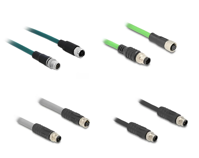
Sensor connectors are essential components in industrial automation systems, designed to provide stable power and signal transmission between sensors, actuators, and control equipment. Most sensor connectors feature a circular design and are available in both metal and plastic housings.
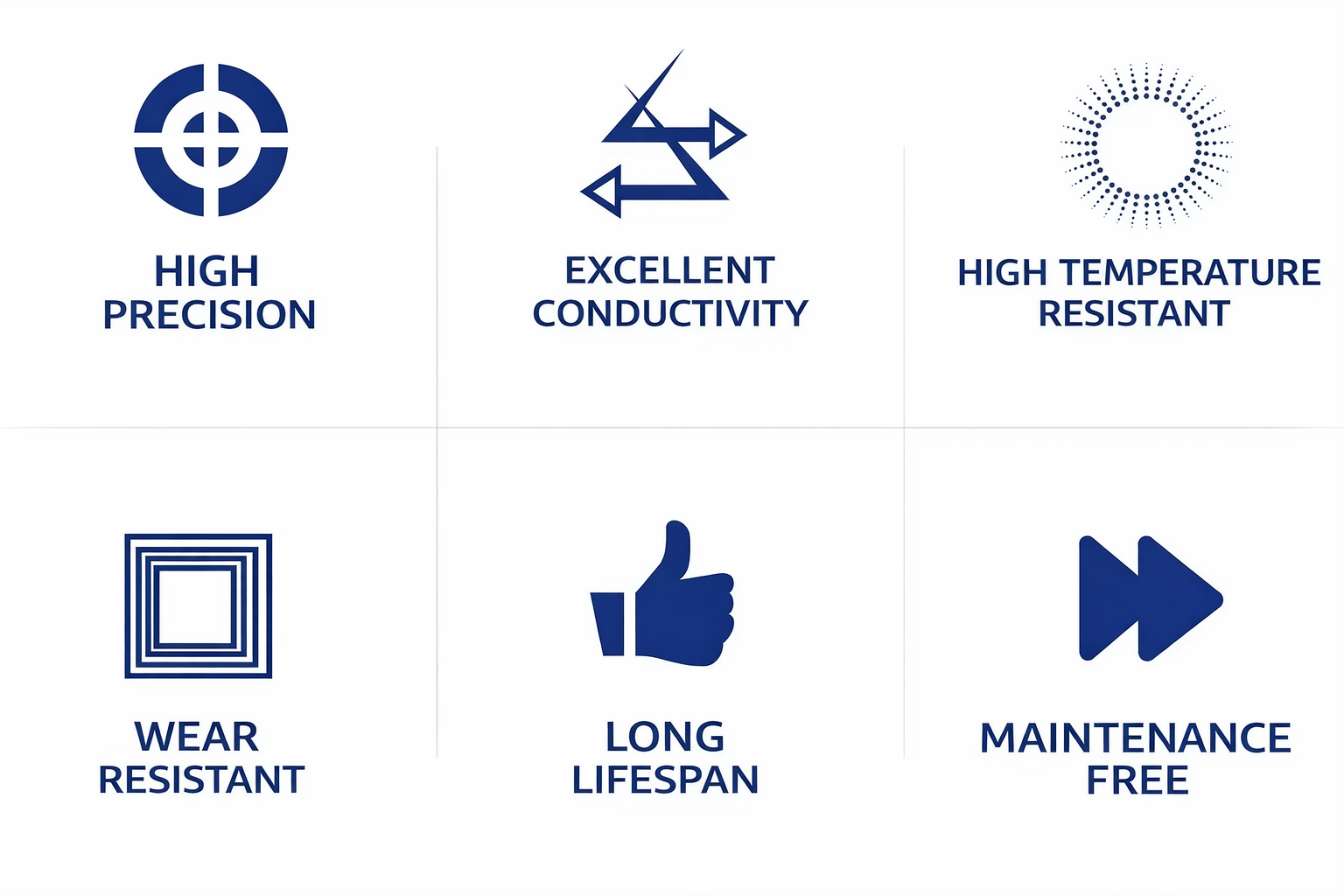
These connectors typically comply with standards such as IEC61076-2-101/104 and offer high protection levels like IP67 or IP68, ensuring reliable performance in harsh environments.
1.1 Key Features of Sensor Connectors
- Waterproof and dustproof (IP67/IP68 rated)
- Threaded locking for secure connection
- Oil-resistant and corrosion-resistant materials
- Stable signal and power transmission
- Suitable for fieldbus systems
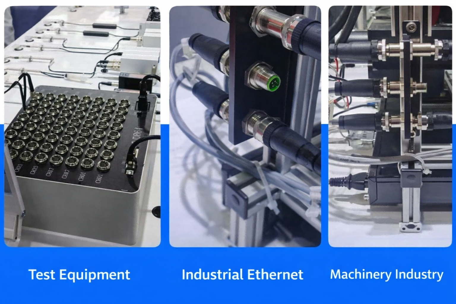
1.2 Common Applications in Industrial Automation
Sensor connectors are widely used in:
- Industrial automation systems
- PLC control cabinets
- Sensors and actuators
- Robotics and manufacturing equipment
- Outdoor and harsh environment installations
2. Sensor Connector Types and Structures
Understanding the structure of sensor connectors is critical for proper assembly and selection.
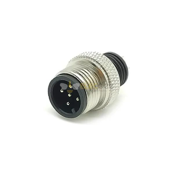
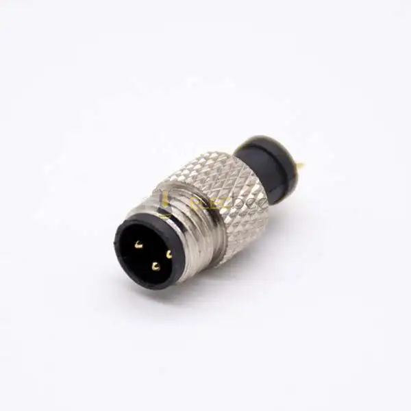
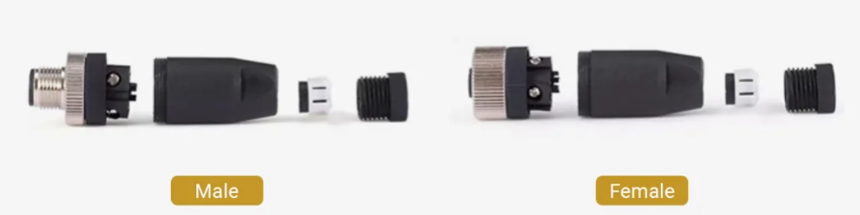
2.1 Plug vs Socket Design
Sensor connectors are divided into:
- Plug (male connector)
- Socket (female connector)
Both are designed to ensure secure mating and stable electrical contact.
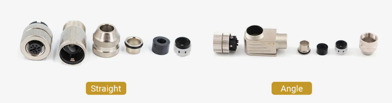
2.2 Straight vs Right-Angle Connectors
- Straight connectors: Ideal for direct connections with enough space
- Right-angle connectors: Perfect for compact installations or tight spaces
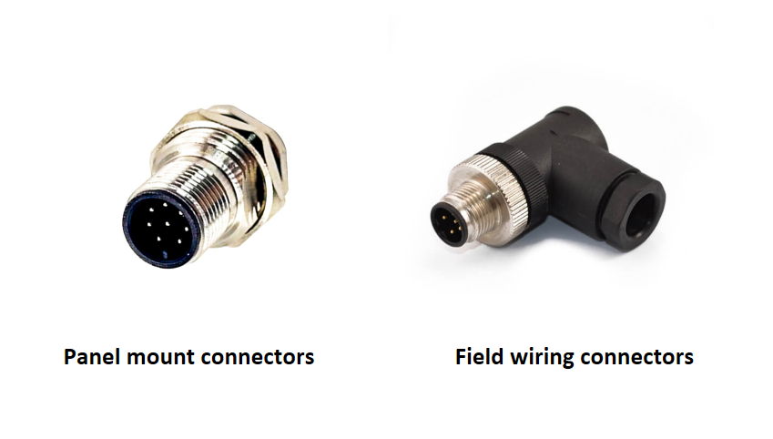
2.3 Panel Mount vs Field Wiring Types
Sensor connectors are typically classified into:
- Panel mount connectors (fixed installation)
- Field wiring connectors (flexible wiring in the field)
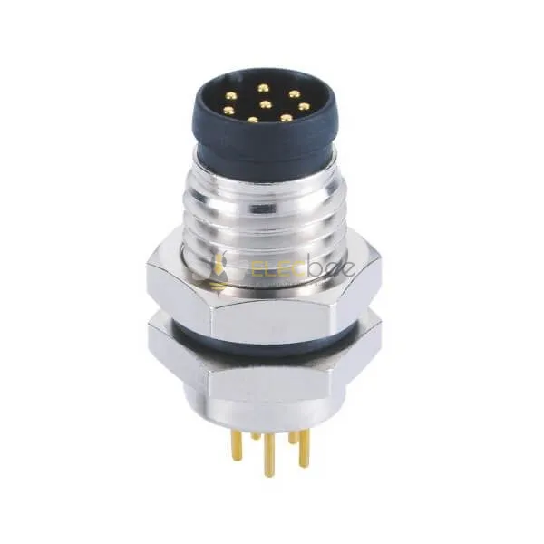
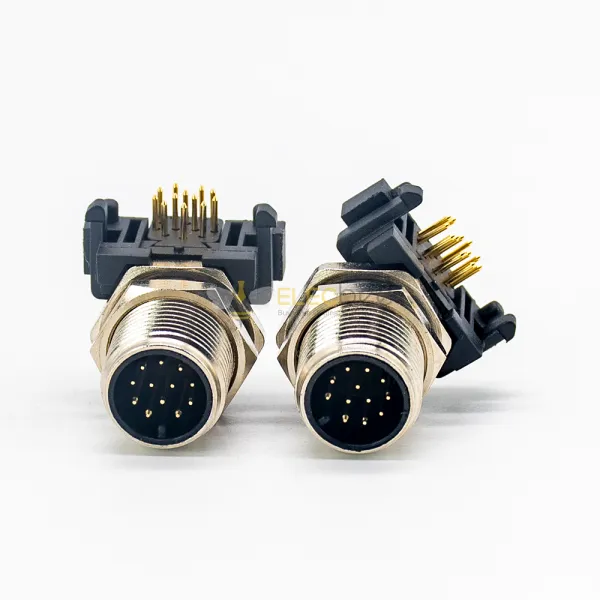
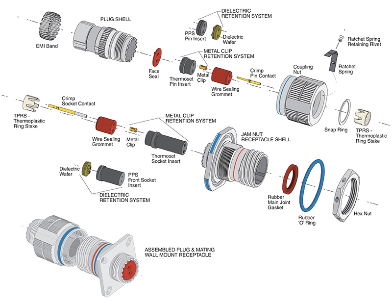
3. M Series Panel Receptacle Assembly Guide
M series connectors (such as M8 and M12) are widely used in industrial environments due to their compact size and reliability.
3.1 Panel Mount Connection Methods
Panel receptacles can be installed using different locking methods:
- Nut locking (with washer)
- Flange mounting (square, round, multi-hole configurations)
These methods ensure a secure mechanical connection between the connector and the panel.
3.2 Center Pin Connection Options (PCB & Cable)
The center conductor can be connected in several ways:
- Wire connection
- Through-hole (plug-in) PCB connection
- Screw-lock connection
Each method is suitable for different application scenarios and installation requirements.
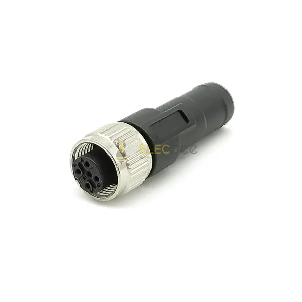
4. Field Wiring Sensor Connectors Explained
Field wiring connectors offer flexibility for on-site installation and customization.
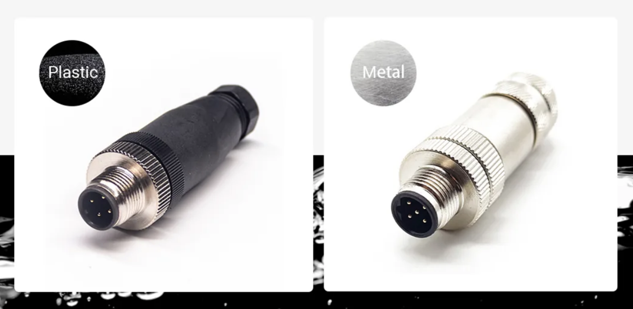
4.1 Metal vs Plastic Housing (Shielded vs Unshielded)
- Metal housing (shielded connectors)
- Provides 360° EMI shielding
- Ideal for high-interference environments
- Plastic housing (unshielded connectors)
- Lightweight and cost-effective
- Suitable for general applications
4.2 Assembled Cable vs Molded Cable
Sensor connectors can also be categorized based on cable configuration:
Assembled Cables
- Custom cable length based on project needs
- Flexible for on-site wiring
- Available in PVC or PUR materials
Molded Cables
- Pre-defined cable lengths (e.g., 1m, 2m, 5m, 10m)
- Strong sealing and durability
- Available in multiple colors (black, blue, orange, etc.)
- Internal structure can be shielded or unshielded
5. How to Choose the Right Sensor Connector Cable
Selecting the correct cable is crucial for performance and durability.
5.1 PVC vs PUR Cable Materials
- PVC cables
- Cost-effective
- Suitable for general indoor use
- PUR cables
- Oil-resistant and abrasion-resistant
- Ideal for industrial and harsh environments
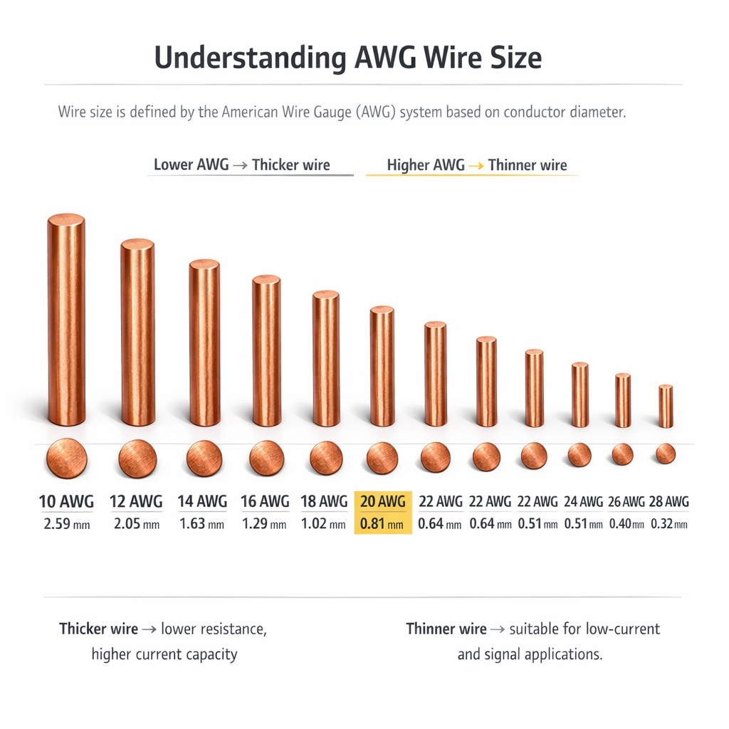
5.2 Understanding AWG Wire Size
Wire size is measured using the AWG (American Wire Gauge) system.
- Higher AWG number → thinner wire
- Lower AWG number → thicker wire
For example:
- 24AWG → thinner wire
- 20AWG → thicker wire
Choosing the correct AWG ensures proper current handling and reduces signal loss.
6. Best Practices for Reliable Sensor Connector Assembly
6.1 Ensuring Waterproof Performance (IP67/IP68)
To maintain waterproof performance:
- Ensure proper sealing during installation
- Tighten threaded connections securely
- Avoid damage to sealing rings
6.2 Installation Tips for Harsh Environments
- Use shielded connectors in high EMI environments
- Choose PUR cables for oil exposure
- Ensure correct cable bending radius
- Regularly inspect connectors for wear or damage
7. Conclusion: Choosing the Right Sensor Connector for Your Application
Sensor connectors play a critical role in ensuring reliable connections in industrial systems. By understanding connector types, assembly methods, cable options, and AWG selection, you can significantly improve system stability and longevity.
Whether you are working with M12 connectors in automation systems or customizing field wiring solutions, selecting the right configuration will ensure optimal performance even in the most demanding environments.