0
0
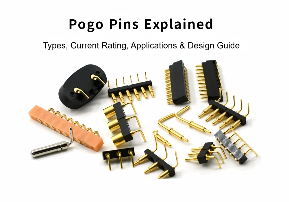
Pogo pin connectors are small spring-loaded electrical contacts used when a device needs a reliable temporary connection instead of a permanent cable or fixed connector. They are widely used in charging docks, PCB testing fixtures, wearable devices, battery contacts, modular electronics and compact industrial systems.
At first glance, pogo pins look simple: a tiny metal pin that moves up and down. In real product design, however, choosing the right pogo pin connector is not just about pin count or size. Engineers must consider current rating, contact resistance, spring force, plating, mating cycles, side load, PCB mounting style, contamination, vibration and the mechanical structure around the contact.
This guide explains how pogo pins work, the main types available, how to evaluate pogo pin current rating, where they are commonly used, and what design mistakes can lead to unreliable contact.
1. What Is a Pogo Pin Connector?
A pogo pin connector is a spring-loaded contact designed to create an electrical connection through compression. When the pin is pressed against a mating pad, the internal spring pushes the plunger outward and maintains contact force between the two conductive surfaces.
Pogo pins are also commonly called spring loaded pins, spring contacts or spring loaded connectors. In many product catalogs, “pogo pin” refers to the individual spring-loaded contact, while “spring loaded connector” may describe either a single contact or a multi-pin connector assembly.
1.1 Pogo Pins vs Spring Loaded Connectors
A pogo pin is usually one type of spring loaded connector. The terms are often used interchangeably, especially in electronics sourcing, but they are not always identical. A single cylindrical spring contact may be called a pogo pin, while a molded multi-pin assembly may be called a spring loaded connector or pogo pin connector.
For SEO and product search, both terms matter. Engineers may search for “pogo pin connector,” “spring loaded connector,” “spring contact,” or “spring loaded pin” depending on their industry background.
Looking for different spring-loaded contact options? Explore our Pogo Pin Connectors & Spring Loaded Contacts for compact PCB designs, charging docks, test fixtures and modular electronics.
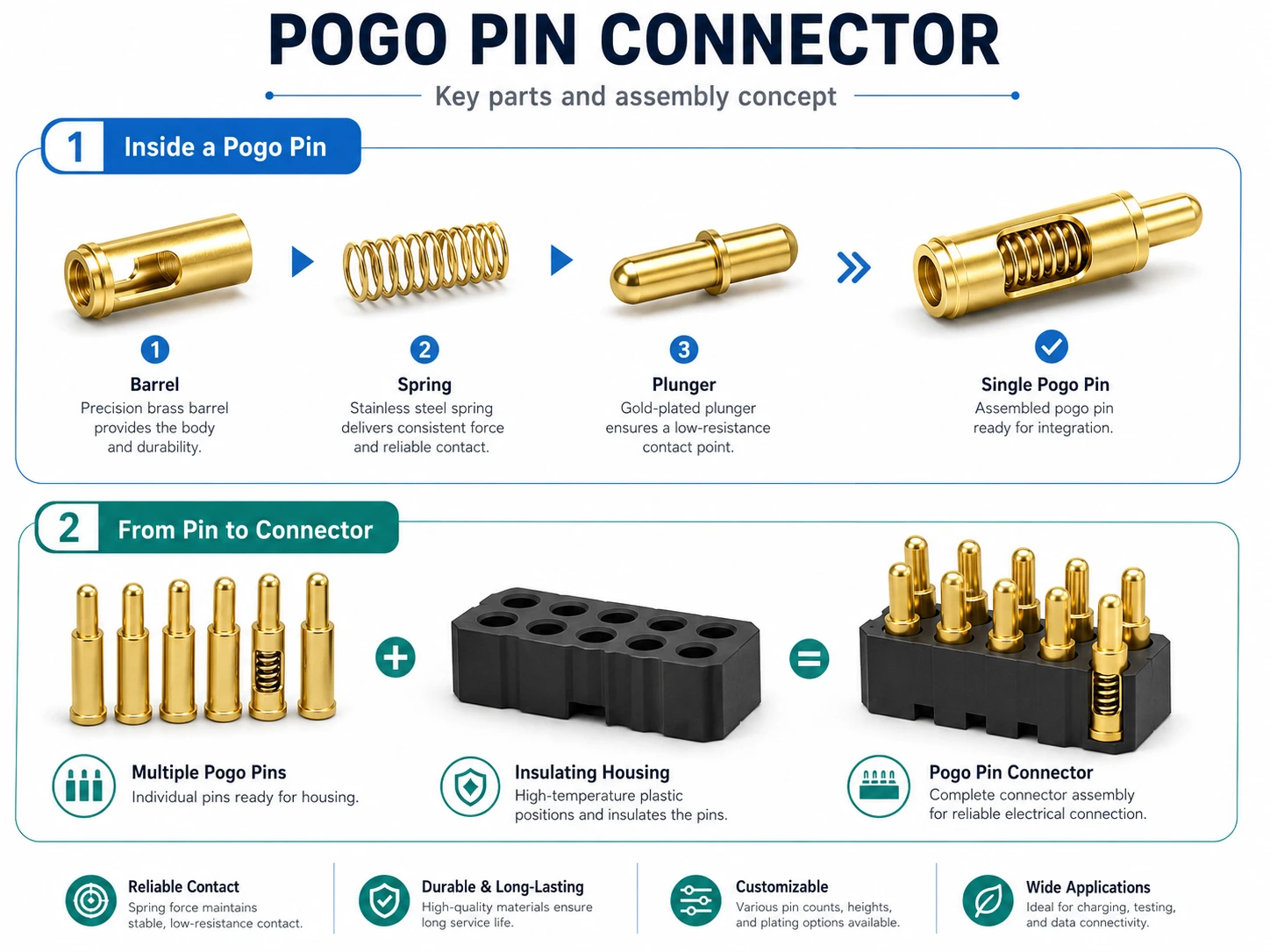
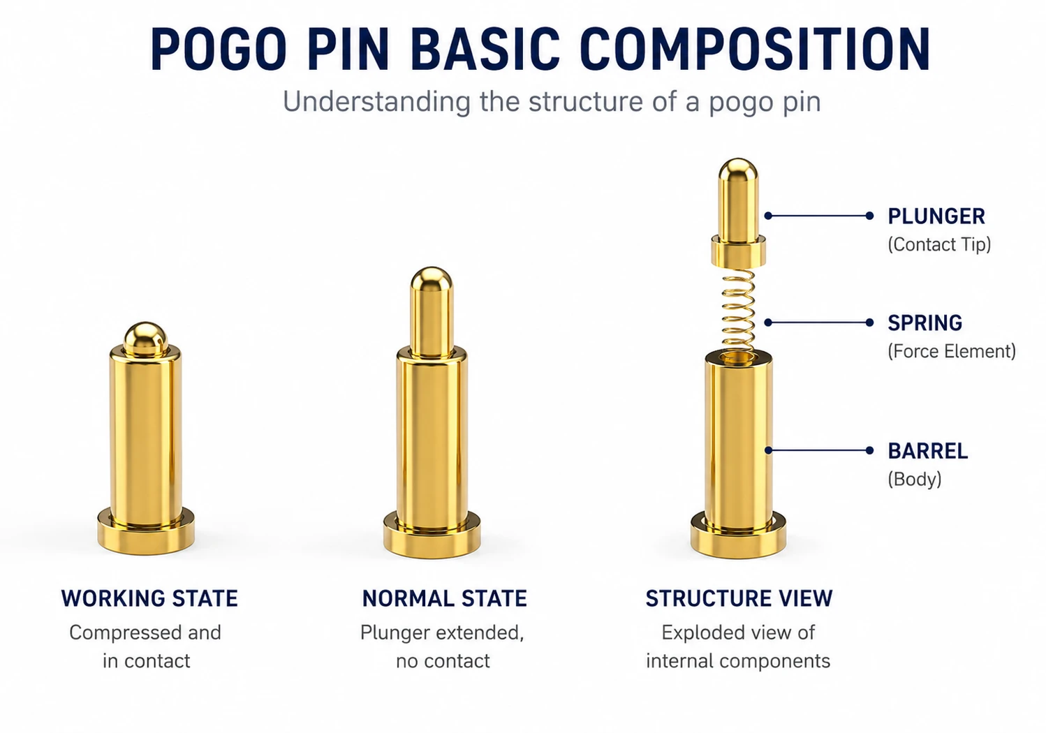
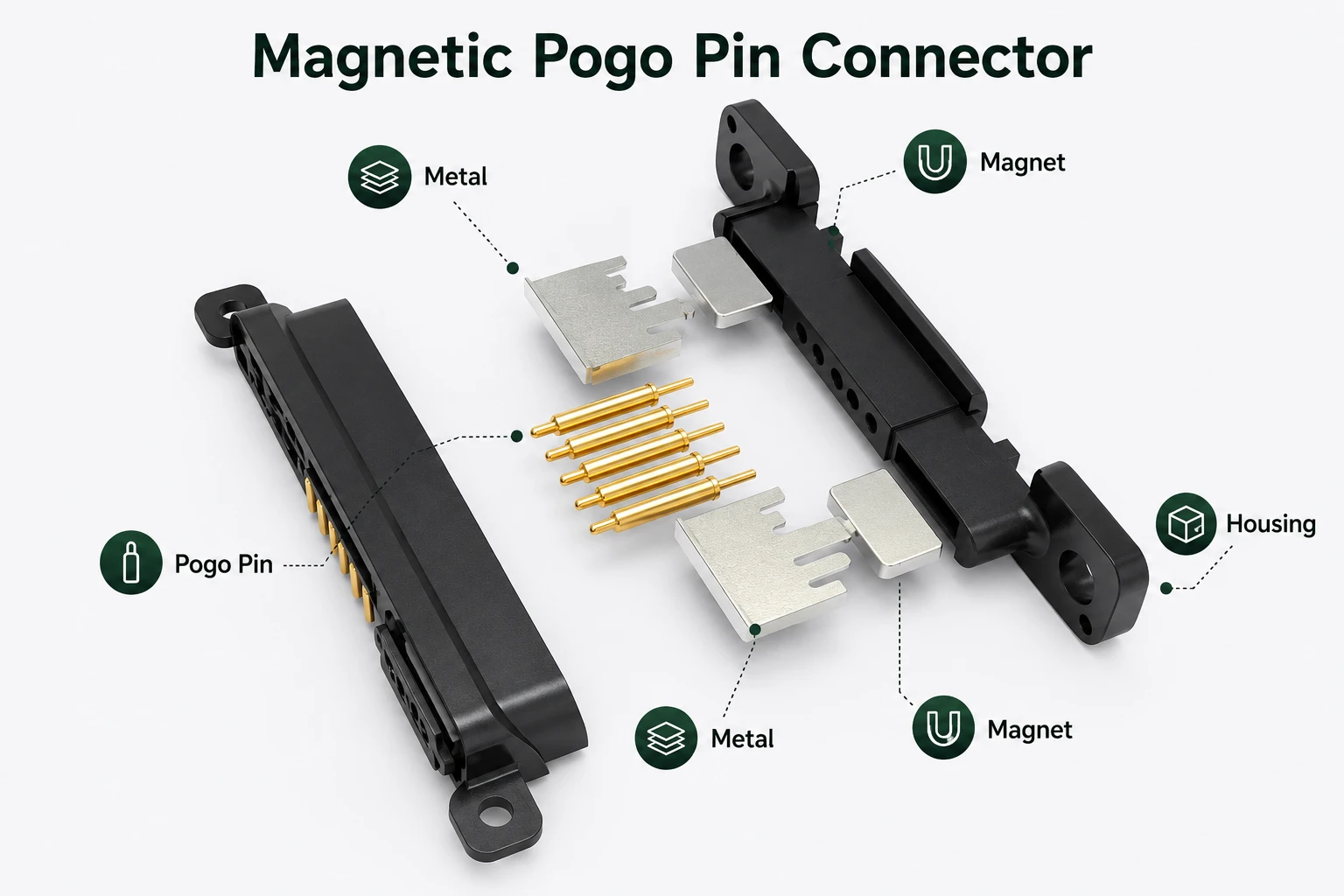
1.2 Main Structure of a Pogo Pin
A typical pogo pin includes three main parts:
- Plunger: The moving contact tip that touches the mating pad.
- Barrel: The outer body that guides the plunger and connects to the PCB or wire.
- Spring: The internal part that provides compression force.
The quality of these components affects electrical resistance, durability, contact stability and mechanical life.
2. How Do Pogo Pins Work?
Pogo pins work by maintaining electrical contact through spring compression. When the device is docked, the pin compresses and presses against a flat pad, metal contact, PCB land or target surface. This pressure creates a conductive path for power, ground or signals.
2.1 Compression Contact Principle
Unlike a traditional plug-and-socket connector, a pogo pin does not usually “insert” into a mating connector. It presses against a target. This makes pogo pins useful for temporary connections, fast docking and repeated contact in test fixtures.
However, this also means the mechanical design around the pogo pin is extremely important. The housing, fixture or enclosure should guide the mating parts so that the pogo pin sees mostly axial compression rather than side force.
2.2 Contact Resistance and Spring Force
Contact resistance is one of the most important performance factors in a pogo pin connector. Higher resistance can cause voltage drop, signal instability or heat generation under load.
Spring force helps maintain stable contact, but more force is not always better. Too little force may cause intermittent contact. Too much force may increase wear, stress the PCB, or make docking difficult. The best design balances contact force, mating cycle life and mechanical support.
2.3 Why Mating Pads Matter
The mating surface is just as important as the pogo pin itself. A poor target pad can wear, oxidize or accumulate contamination over time. For reliable designs, engineers often use gold-plated pads, dedicated target contacts or a controlled contact surface instead of relying on a random PCB trace or untreated metal surface.
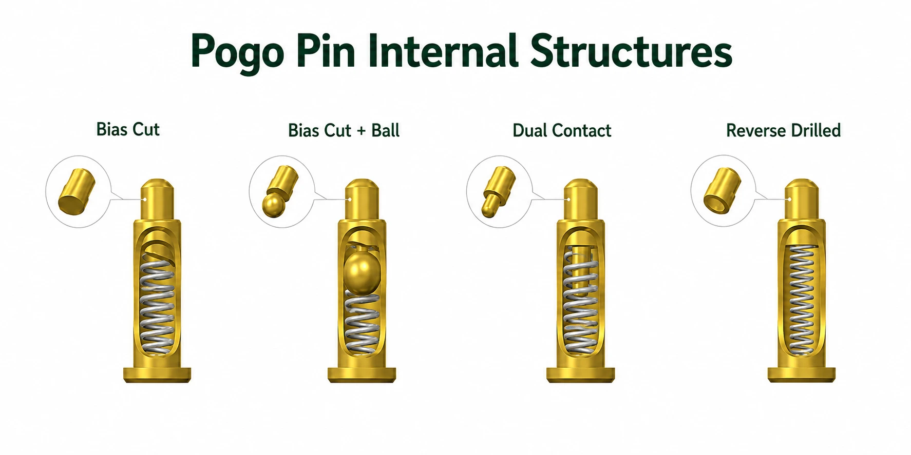
2.4 Internal Contact Structures of Pogo Pins
Different pogo pin designs use different internal contact structures to improve contact stability, reduce resistance and control spring performance. Common designs include bias-cut contact, ball-assisted contact, dual-contact structure and reverse-drilled structure. The best structure depends on current requirement, contact stability, size limitation and expected mating cycles.
3. Main Types of Pogo Pins
Pogo pins are available in different mounting styles and mechanical formats. The right type depends on PCB space, current requirement, mechanical stress and application environment.
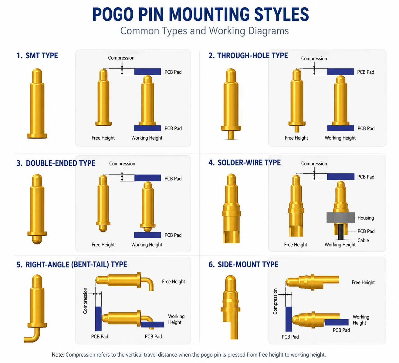
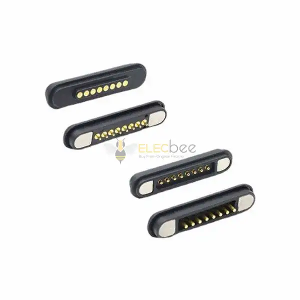
3.1 SMT Pogo Pins for Compact PCB Design
SMT pogo pins are mounted directly on the surface of the PCB. They are suitable for compact devices, wearable electronics, small charging contacts and high-density layouts.
The main advantage of SMT pogo pins is space efficiency. They are easy to place in compact PCB designs and can support automated assembly. The main risk is mechanical stress. If the pogo pin receives side load or the device is docked roughly, the solder joint or pad may be damaged.
3.2 Through-Hole Pogo Pins for Stronger Retention
Through-hole pogo pins use pins or tails that pass through the PCB and are soldered from the other side. They usually provide stronger mechanical retention than SMT contacts and are often preferred when the contact may experience higher mechanical stress.
The tradeoff is that through-hole designs require drilled holes, more PCB space and sometimes extra assembly steps. For rugged docking systems, through-hole mounting can be a safer choice if the product design allows enough space.
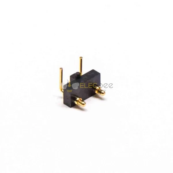
3.3 Right-Angle and Bent-Tail Pogo Pins
Right-angle pogo pins are used when vertical height is limited or the contact direction needs to change. They can be useful in tight packaging, but they also introduce mechanical leverage. Without proper support, the bent area or solder termination can become a stress concentration point.
For right-angle designs, it is better to use a supported right-angle pogo pin header or add a housing feature, bracket or mechanical clamp that prevents the pin from carrying bending force by itself.
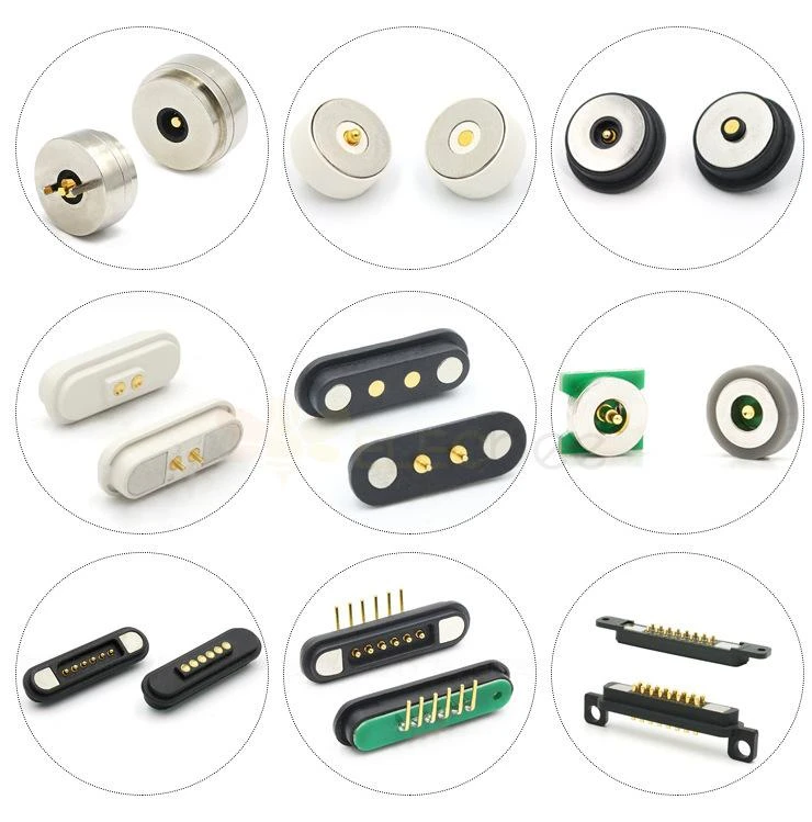
3.4 High-Current and Magnetic Pogo Pin Connectors
High-current pogo pins are larger and designed with lower resistance contact paths. They are used in charging docks, battery connections and power transfer applications. Magnetic pogo pin connectors combine magnets with spring contacts to improve alignment in docking or charging systems.
However, not every pogo pin is suitable for high current. Standard small pogo pins should not be treated as power terminals unless their datasheet clearly supports the required current, temperature rise and duty cycle.
| Type | Best For | Advantages | Risks |
|---|---|---|---|
| SMT Pogo Pin | Compact PCB design, wearables, small charging contacts | Low profile, space-saving, suitable for automated assembly | Solder joint fatigue or pad lift under side load |
| Through-Hole Pogo Pin | Rugged docking, stronger mechanical retention | Better retention and easier rework | Larger footprint and extra drilling cost |
| Right-Angle Pogo Pin | Height-limited layouts and side-contact designs | Flexible packaging direction | Needs mechanical support to avoid bending stress |
| High-Current Pogo Pin | Battery charging and power transfer | Designed for higher current and lower resistance | Requires thermal validation and proper contact design |
Need Different Pogo Pin Connector Types?
Browse SMT, through-hole, right-angle, magnetic and multi-pin pogo pin connectors for PCB contact, charging docks and testing applications.
4. Pogo Pin Current Rating: What Really Matters?
Pogo pin current rating tells you how much current a pin can carry under specified conditions. But in real applications, the safe current depends on more than a number in a catalog.
4.1 Current Rating Is Not Only About Pin Size
Pin diameter, material, plating, spring structure, contact area and mating surface all affect current capacity. A larger contact usually handles more current, but design details such as contact resistance and heat dissipation are just as important.
If a product needs high current for charging, battery connection or power transfer, choose pogo pins specifically designed for high-current applications. Do not assume that a standard signal pogo pin can safely carry several amps.
4.2 Contact Resistance, Heat and Voltage Drop
When current flows through contact resistance, heat is generated. Higher resistance increases voltage drop and temperature rise. This becomes more serious after repeated mating cycles, contamination or plating wear.
For power applications, engineers should evaluate voltage drop under load and temperature rise during worst-case operation. A pogo pin that works on a clean bench may behave differently after dust, sweat, vibration or thousands of docking cycles.
4.3 Can You Parallel Pogo Pins for More Current?
Using multiple contacts for V+ and GND is common in some designs, but it should not be treated as a simple way to multiply current rating. Current may not share equally across pins. One pin can carry more load due to lower resistance, become hotter, and then continue to carry more current.
If parallel pins are used, the design should include proper layout symmetry, matched contact paths, thermal margin and validation testing. For safety-critical or high-current systems, dedicated high-power contacts may be a better choice.
4.4 How to Validate Current Performance
A practical validation plan may include:
- Measure contact resistance using a 4-wire method.
- Log voltage drop under real load current.
- Test temperature rise at worst-case duty cycle.
- Repeat measurements after mating cycle testing.
- Test under vibration or slight misalignment if the product will experience it.
5. Common Applications of Pogo Pin Connectors
5.1 Charging Docks and Wearable Devices
Pogo pins are widely used in charging docks for earbuds, smartwatches, handheld devices, scanners and portable instruments. They provide a compact connection for both power and low-speed signals.
For charging applications, the moving spring contacts are often placed on the charger or dock side, while the device uses flat plated pads. This makes the lower-cost accessory easier to replace if the moving contacts wear out.
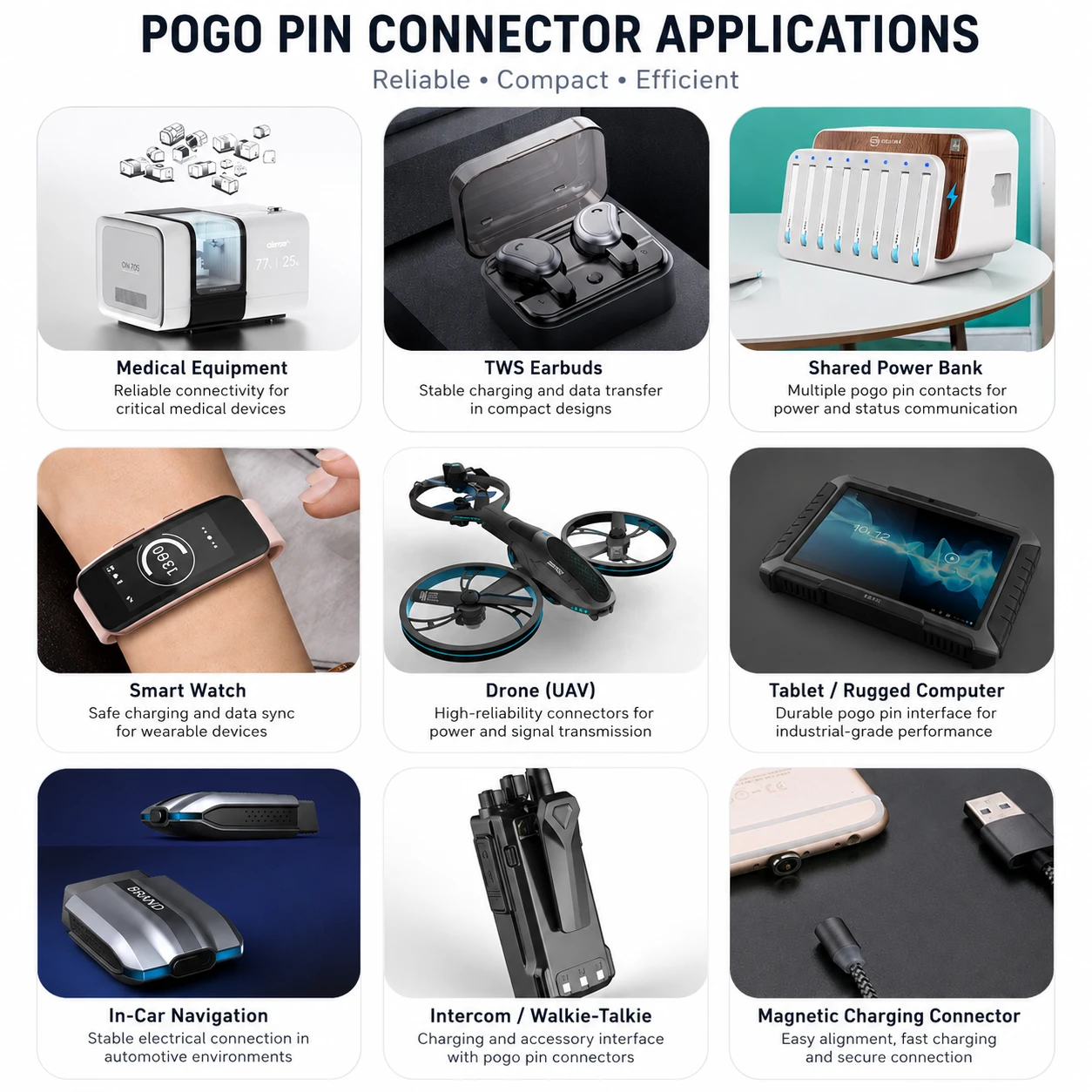
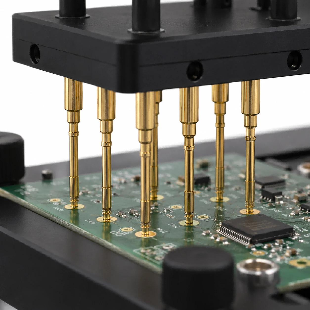
5.2 PCB Testing Fixtures
Test fixtures are one of the classic applications for pogo pins. A bed-of-nails fixture uses spring probes to contact test pads on a PCB. This allows fast electrical testing without soldering wires to every board.
In this use case, pogo pins are usually part of a controlled fixture, not an exposed consumer interface. The environment is cleaner, alignment is controlled and the contacts can be maintained or replaced.
5.3 Board-to-Board and Modular Devices
Pogo pins can be used for board-to-board contact in modular products, but the mechanical design must be carefully controlled. In vibration environments, such as automotive or industrial equipment, the boards should be mechanically fixed so that the pogo pins do not experience constant relative movement.
If the application requires permanent board-to-board connection under vibration, floating board-to-board connectors, flex cables or wire harnesses may be more reliable than simple pogo pin compression contact.
5.4 Grounding and Enclosure Contact
Pogo pins can also be used as grounding contacts between a PCB and a metal enclosure. This is useful when a design needs removable grounding, shield contact or single-point enclosure connection.
In this case, current is usually low, but contact stability and corrosion resistance still matter. The mating surface should be clean, conductive and mechanically stable.
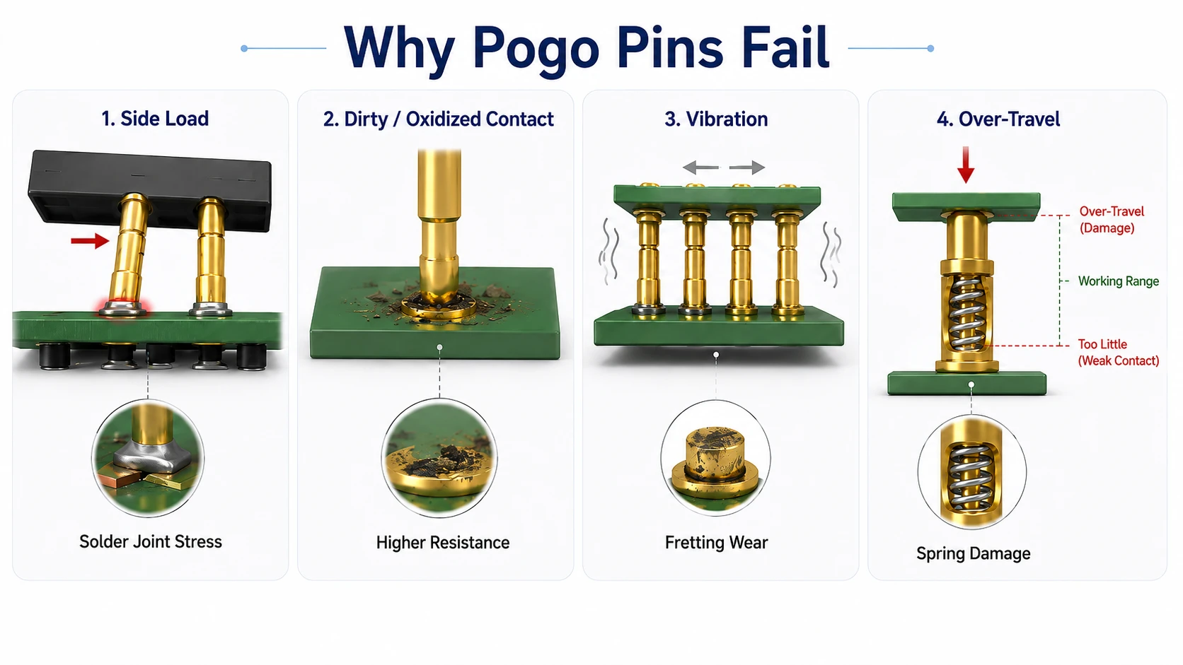
6. Reliability Risks: Why Pogo Pins Fail
Pogo pins can be reliable when used correctly, but they are not universal connectors. Many failures come from using the wrong type of contact for the mechanical environment.
6.1 Side Load and Solder Joint Stress
SMT pogo pins are especially sensitive to side load. If the user docks the device at an angle or the housing does not guide compression properly, lateral force can stress the solder joint or peel the PCB pad.
The best solution is to make the housing carry the side load. The pogo pin should mainly see vertical compression, not bending force.
6.2 Dirt, Oxidation and Lack of Wiping Action
One common weakness of pogo pins is that they do not always provide a strong wiping action. Dirt, sweat, grease, dust or oxidation on the mating surface can increase resistance or cause intermittent charging.
Gold plating, sealed designs, recessed contacts and user-cleanable surfaces can help, but they do not eliminate the need for good mechanical and environmental design.
6.3 Vibration and Long-Term Compression
In vibration environments, the contact may experience micro-motion. This can lead to intermittent contact, fretting wear or unstable signals. Long-term compression can also stress the spring if the design exceeds the recommended working travel.
For automotive, robotics and industrial equipment, mechanical fixation is critical. Boards should move together as one assembly, or the interconnect should allow controlled movement through flex cables or floating connectors.
6.4 Over-Travel and Poor Mechanical Support
Every pogo pin has a recommended working travel. If the mating part compresses the pin too far, the spring or internal structure may be damaged. If it compresses too little, contact force may be insufficient.
Good designs include mechanical stops, controlled stack-up tolerance and enough housing support to protect the contact.
7. How to Choose the Right Pogo Pin Connector
Choosing a pogo pin connector should start with the application, not the catalog size. Use the following process before selecting a part.
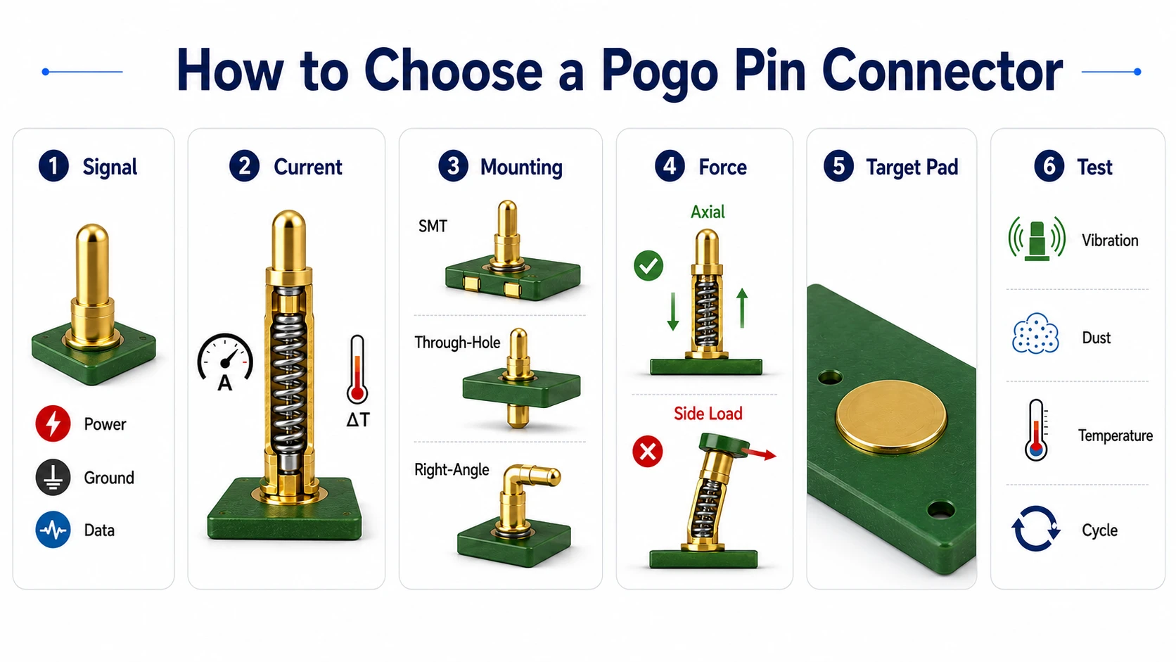
7.1 Selection Checklist
- Define the signal type: power, ground, low-speed data or test signal.
- Check current rating: confirm current per pin, voltage drop and thermal margin.
- Choose mounting style: SMT for compact PCB designs, through-hole for stronger retention, supported right-angle for special packaging.
- Evaluate mechanical force: avoid side load and design for axial compression.
- Confirm mating surface: use suitable plating or target pads.
- Test the real environment: include dirt, vibration, humidity, cycling and temperature rise if relevant.
7.2 Pogo Pins vs Wireless Charging vs USB Connectors
Pogo pins are often compared with wireless charging and USB connectors. Each solution has advantages and tradeoffs.
| Solution | Advantages | Limitations | Best Use Cases |
|---|---|---|---|
| Pogo Pin Connector | Compact, efficient, good for docking and test fixtures | Sensitive to dirt, side load and mechanical wear | Charging docks, wearables, PCB testing, modular devices |
| Wireless Charging | No exposed contacts, sealed design, no mechanical wear | Lower efficiency, heat, coil space and electronics cost | Consumer devices, waterproof products, low-power charging |
| USB Connector | Standardized, supports data and power, widely available | Port wear, insertion damage, sealing challenges | General electronics, data transfer, standard charging |
7.3 Common Design Mistakes to Avoid
- Using standard small pogo pins for high-current charging without validation.
- Allowing side load to act directly on SMT solder joints.
- Ignoring dirt, sweat, oil or oxidation on user-facing contacts.
- Compressing the pin beyond its recommended travel.
- Assuming parallel pins will always share current equally.
- Using pogo pins for vibration-heavy permanent board-to-board connections without mechanical fixation.
FAQ
Are pogo pins the same as spring loaded connectors?
A pogo pin is a type of spring loaded connector. In many cases, the terms are used interchangeably, but “spring loaded connector” can also refer to a complete multi-pin assembly.
How much current can a pogo pin carry?
It depends on the pin size, material, plating, contact resistance, mating surface and thermal design. Small signal pogo pins may only support low current, while high-current pogo pins are designed specifically for power transfer.
Are pogo pins reliable for charging?
They can be reliable in charging docks if the design controls alignment, contact force, contamination and current rating. For dirty consumer environments, sealed or wireless solutions may be more suitable.
Are SMT pogo pins strong enough?
SMT pogo pins are suitable for compact PCB designs when the housing supports the mechanical load. They should not be exposed to strong side forces because the solder joint or PCB pad may fail.
Can pogo pins be used for board-to-board connections?
Yes, but the boards must be mechanically supported. For permanent connections under vibration, flex cables, floating board-to-board connectors or rugged wire harnesses may be better options.
Conclusion
Pogo pin connectors are compact, flexible and useful for temporary electrical connections in charging docks, PCB testing fixtures, wearable devices and modular electronic systems. They are especially valuable when a product needs repeated docking, fast contact or a low-profile connection.
However, pogo pins are not magic connectors. Their reliability depends on current rating, contact resistance, plating, spring force, mating surface, side-load control and environmental protection. A successful design should treat the pogo pin as part of a complete mechanical and electrical system, not just a small metal contact.
For compact PCB layouts, SMT pogo pins are a good choice when the housing controls the load. For rugged mounting, through-hole contacts may offer stronger retention. For charging and power transfer, high-current pogo pins or magnetic pogo pin connectors should be selected and validated carefully.
Choosing the right pogo pin connector depends on your PCB layout, current rating, contact direction and working environment.
Explore related spring-loaded contacts and connector solutions for your next design.
- Pogo Pins & Spring Loaded Connectors
- Battery Chargers
- USB Connectors for Power and Data Transfer
- USB Power Testers & Electronic Loads