0

For a water pump, a soft starter is built for applications that run at fixed full speed once started and need lower starting current or gentler mechanical and hydraulic transitions during startup and, on suitably equipped models, stopping. A variable frequency drive (VFD) is built for systems where you also want to regulate flow or pressure by changing motor speed during operation.
This guide focuses on standard centrifugal water pumps driven by three-phase AC induction motors, rather than single-phase pump motors, pumps with integrated electronic controls, or code-governed fire-pump systems.
Soft Starter vs VFD: Starting and Running a Water Pump
A soft starter and a VFD act on different parts of a pump's operating cycle. As Eaton explains in its comparison of soft starters and variable frequency drives, a soft starter controls the voltage applied to the motor during startup (and during stopping on models configured with a soft-stop function), while a VFD adjusts both frequency and voltage to control motor speed throughout startup, continuous running, and stopping.
When the Task Is Only Smooth Starting and Stopping
Starting a three-phase pump directly across the line draws high inrush current and applies sudden torque to the impeller and coupling. If the pumping system already delivers the required flow at full rated speed, such as a transfer pump filling an elevated storage tank on a steady schedule, continuous speed regulation may be unnecessary. According to Utah State University Extension's guidance on irrigation pump drives, needing soft starting alone typically does not justify the added investment of a VFD when operating demand is fixed.
Lowering starting voltage through a soft starter reduces initial current and torque so the motor accelerates more gradually, though motor speed and water flow still follow the torque balance between the motor and the pump load instead of rising in a straight line with voltage. Once the startup transition finishes, the motor runs at full rated speed.
During shutdown, abrupt pump stops or rapid valve closures can trigger pressure transients (water hammer) in the piping. A soft starter can help ease stopping transitions if the chosen model includes a soft-stop function, though a basic voltage ramp down does not resolve pressure surges in every pipe layout. As ABB notes regarding typical pump problems, certain pump-oriented soft starters (such as ABB's PSTX series) incorporate specialized torque control or soft pipe-filling profiles to limit pressure transients. Because capabilities vary across product lines, check how the controller's stopping profile interacts with your check valves and piping elevation rather than assuming any generic soft starter or default VFD ramp will eliminate water hammer.
When the Task Involves Adjusting Flow or Pressure by Speed
Pumping systems can accommodate changing demand through several methods, including cycling fixed-speed pumps with a storage tank, throttling discharge valves, using bypass lines, or varying pump speed. If you choose to regulate operating flow or pressure by changing the pump's rotational speed, for instance matching irrigation delivery across different field zones or holding header pressure as downstream usage shifts, you need a compatible variable-speed system.
A standalone VFD unit is the motor controller, not a complete constant-pressure pumping station on its own. Automating pressure or flow regulation also requires compatible sensors, control logic (configured inside the drive or through an external controller), and pump-system protections.

These profiles explain the control difference; they are not measured speed, pressure or voltage traces. Phase durations and ramp shapes vary with the installation.
How Pump Curves and Static Head Affect VFD Energy Savings
How a centrifugal pump responds to speed changes depends on the resistance of the piping system. As outlined in the Hydraulic Institute’s explanation of system curves, system resistance combines static head (vertical elevation lift or constant backpressure that exists regardless of flow) and friction head (resistance from pipes, fittings, and valves that rises with flow rate).
In an idealized friction-dominated system, such as a long horizontal transfer line with minimal elevation lift, flow changes roughly in proportion to pump speed and shaft power drops steeply as speed is reduced. When static head makes up a large share of total system head, such as lifting water into an overhead tower or feeding a pressurized tank, the pump must maintain enough rotational speed to generate head above that fixed elevation or pressure threshold. If pump head falls below the required static head, it cannot deliver the target flow against system backpressure. As a result, high static head can narrow the usable speed range, flow no longer scales in simple one-to-one proportion with speed, and applying textbook cube-law formulas directly can seriously overestimate energy savings, as the DOE/HI/Europump variable-speed pumping guide explains.
Evaluating a VFD under static head requires checking the pump curve alongside your system curve. As Grundfos explains in its overview of pump performance curves, a pump curve maps flow (Q) against head (H), and variable-speed operation shifts that curve across different speed bands so you can see where the operating point lands at reduced speeds. Because the Q-H curve alone does not define thermal or mechanical boundaries, check the pump and motor manufacturer documentation separately for minimum allowable flow, minimum speed, and motor cooling limits at reduced RPM.
Note that these centrifugal curve relationships and throttling behaviors do not apply to positive displacement pumps (such as plunger or gear pumps), which move a nearly fixed volume per revolution and require different sizing rules.

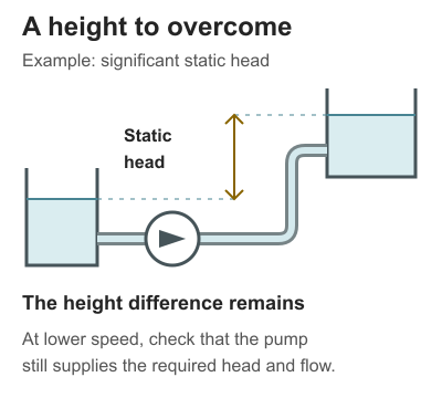
Conceptual open-tank examples, not installation drawings or scaled layouts. Elevation is one source of static head; a fixed pressure difference can also contribute.
Matching the Motor and Reading a Drive Specification Page
Power Supply Phases and Motor Compatibility
Start with the motor nameplate and site power supply:
- Three-phase supply with a three-phase motor: Match the controller's input/output voltage and continuous current capability to the motor's rated voltage and full-load amperage (FLA), accounting for starting duty and ambient conditions.
- Single-phase supply with a three-phase pump motor: In a three-phase motor application, a standard soft starter does not convert single-phase power into three-phase output. If you need to run a three-phase pump motor from a single-phase line, see our single-phase to three-phase VFD sizing and motor guide for phase-conversion sizing and derating requirements.
- Single-phase or integrated-electronics motors: Do not pair a standard three-phase VFD or soft starter with a single-phase capacitor motor or a pump with built-in electronic speed control unless the pump manufacturer explicitly confirms compatibility.
Reading the Listing and Checking the Manufacturer’s Manual
When browsing the VFDs and Soft Starters category on Elecbee, use the product page to screen basic voltage and phase class, then verify pump-specific operating details in the manual before ordering.

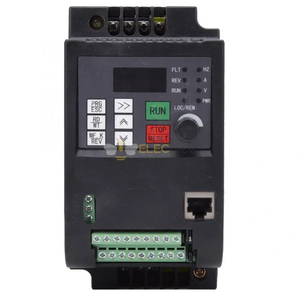
Photo from the linked product listing. Appearance does not establish pump compatibility.
Consider the page listing for the 0.75 kW (1 HP) Three-Phase 380V Variable Frequency Drive (EB-VF01-96M-3T-00075) as an example:
- Initial voltage and phase screening from the page: The listing specifies three-phase 380V AC input, three-phase 0–380V AC output, a nominal power rating of 0.75 kW / 1 HP, a
Rated Currentfield of2.5A, and RS485/Modbus communication. Those listed input/output voltage and phase fields let you check whether the drive matches a three-phase 380V power supply and motor voltage class. - Current definition and pump control details to confirm in the manual: Because the page lists
Rated Current: 2.5Awithout stating its continuous-duty condition or overload definition, you cannot confirm motor current alignment from the summary table alone; continuous output current and duty derating must be checked in the manual first. You should also verify the enclosure protection (IP rating) for your mounting location, analog or sensor input terminals if wiring a pressure transducer, and whether pump-specific functions such as dry-run protection or sleep/wake logic are supported by the drive or require external control hardware.
Details to Prepare When Confirming an Application
If you use Elecbee's contact page to check manual specifications or clarify unresolved functional questions before purchasing, include the following information with your inquiry:
- Motor nameplate data: Rated voltage, phase count, frequency, power (kW/HP), and full-load amperage (FLA).
- Pump type and curve data: Centrifugal vs. other pump construction, rated flow and head, and the approximate share of static lift vs. pipe friction in your system.
- Target control method: Fixed-speed starting/stopping relief or variable-speed flow/pressure regulation, along with any sensor signal requirements.
- Operating environment and start duty: Ambient temperature, enclosure requirements, and expected starts per hour.