

 0

For a positive, non-isolated DC supply, compare the voltage at the module’s input pins with the voltage your load needs. If the input stays above the target with enough headroom at full load, choose a buck converter to step it down. If it stays below, choose a boost converter to step it up. If it crosses the target and the output must stay regulated throughout, use a non-inverting buck-boost converter.
Which converter fits your input range?
Example voltages at the module pins, on a common 0–12 V scale.
Buck

Check input limits, headroom at full load and continuous output current.
Boost

Check startup and continuous output capability at 3.0 V.
Non-inverting buck-boost

Check for a positive output and regulation through the 3.3 V crossover.
What changes besides voltage?
The same 5 V, 1 A load uses 5 W whether it is fed through a buck converter or a linear regulator. On a 12 V supply, the two approaches draw different currents and release different amounts of heat.
For the buck, size the supply for the input current and the board for the output current. For the linear regulator, the demanding part of this example is getting 7 W of heat out of the regulator.
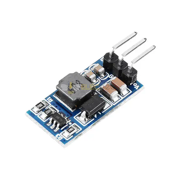
For a regulated 12 V supply feeding a 5 V, 1 A load, consider Elecbee’s fixed 5 V buck module (EB0044142). Its listing specifies a 7–26 V input and recommends staying within 1.6 A for extended operation. The 3 A figure is the maximum. Check cooling in your enclosure.
In a conventional buck or boost circuit, the switch controls when the inductor stores or releases energy. The two examples use a diode and an output capacitor (C). Follow the switch from the supply side in the buck circuit to the return side in the boost circuit.
Buck

Boost

How to measure the input voltage range
The voltage printed on a battery or supply does not tell you the full range at the module. Two separate factors shift that voltage: source variation and path loss. A battery or unregulated supply can sit well above its nominal label when fully charged or lightly loaded—such as a nominal 3.7 V lithium-ion cell starting near 4.2 V—and then droop as it discharges or delivers heavy current. Between the source and the converter, wire resistance, connectors, fuses, and battery protection switches drop additional voltage whenever current flows.

To find the lowest terminal voltage under full load, either measure directly across the converter's input pins while the system draws maximum load near the end of discharge, or estimate it from the loaded voltage at your chosen source measurement points by subtracting the total supply and return path drop between those points and the module pins.
Count that round-trip path drop once; do not subtract lead loss a second time if your voltage reading was already taken at the converter end of the cable. Also check the highest input voltage at full charge and light or no load to make sure it stays within the module's maximum input rating.
Compare both ends of that measured range with the target. A boost-only board cannot step a high input down. At the low end of a buck supply, the decisive number is how much extra input voltage the particular board needs under load. This is its dropout headroom.
Will 5.10 V in sustain a 5 V output?
Suppose a load accepts 5.00 V ±5%, or 4.75–5.25 V at its pins. Under full load the module input falls to 5.10 V. The candidate buck needs 0.30 V of headroom at that current to hold its 5.00 V setpoint.

That shortfall tells you where the 5.00 V guarantee ends. It does not predict a 4.80 V output. The regulator may track the input, lose regulation under transient load, or reach its undervoltage shutdown threshold. Check the manufacturer’s dropout behavior at the current you need.
If the load requires a regulated 5.00 V, first check whether reducing wiring loss can keep the input above 5.30 V, or whether a different buck has a specified dropout within the available 0.10 V. If the source can swing below the target, consider a non-inverting step-up/step-down board.
If the load can use the full ±5% tolerance, use the documented output behavior and the drop in the output leads to check both the 4.75 V lower limit and the 5.25 V upper limit at the load. A board can meet a load’s tolerance even when it falls out of regulation, provided the voltage stays inside that window throughout operation.
When the battery voltage crosses the output voltage
When the terminal input voltage straddles the target output—starting above 3.3 V when a cell is fresh and falling below 3.3 V as it discharges under load—tight full-range regulation requires both step-down and step-up operation.
Before selecting a module labeled "buck-boost," confirm two specifications. First, verify that the output is positive (non-inverting), because the classic single-inductor buck-boost circuit topology produces a negative output voltage relative to common ground. Second, confirm that the regulator maintains clean, continuous regulation as the input voltage passes through the target output voltage. Non-inverting operation does not require a four-switch circuit, so judge a candidate board by its specified crossover regulation rather than assuming its internal switch arrangement.
Can the source power the load at its lowest voltage?
For the same output power and comparable efficiency, a regulated DC-DC converter draws more input current as input voltage falls. That means you should evaluate both your power source and the converter module at the lowest expected terminal input voltage using the converter's actual efficiency (as a decimal) at that operating point, alongside all other specified limits:
Average input current (A) = output voltage (V) × load current (A) ÷ [lowest input voltage at the module (V) × efficiency]
Suppose a load needs 5 V at 1 A (5 W) when the module input has fallen to 3.0 V. For both cases below, assume 85% efficiency at the operating point. Use 0.85 in the formula.
To deliver 1 A at 5 V

Source limited to 1.50 A continuous

The calculation checks the source’s steady-state power. Next establish whether the board can deliver the continuous load at the expected temperature and airflow, and whether the system can start at the lowest input voltage.
What does “2 A” mean on a module datasheet?
For the 5 V, 1 A load in the example, the load draws 1 A while the 3.0 V source supplies about 1.96 A on average. Inside the boost stage, the inductor current rises and falls each switching cycle, so the switch sees a higher instantaneous peak. A module labeled “2 A” could be describing any of these currents. The parameter name and test conditions tell you which one.
Consider two hypothetical listings for that load.
- Board A gives only a “2 A” headline. Ask for the continuous output rating at 3.0 V input and 5 V output, with the cooling conditions. Until you have that information, the board’s ability to power this load is uncertain.
- Board B provides operating curves. On the output-current graph, choose the 5 V output curve and find 3.0 V on the input axis. Compare the current at that point with the 1 A load. Then read efficiency for that input and load to estimate the source current. Check whether the graph represents typical performance or a guaranteed rating, and whether the test cooling matches your enclosure.
Look up the minimum voltage for starting with a load attached. Compare the expected inrush pulse with the source’s pulse-current rating and check how far the voltage at the module pins can dip. A board that keeps running from a depleted battery can still struggle to restart from it. TI’s boost startup measurements
TI’s TPS61022 illustrates how to read the specification. The datasheet specifies the valley switch-current limit at 3.6 V input and 5 V output. “Valley” means the low point of the inductor current in a switching cycle.
| Minimum | Typical | Maximum |
|---|---|---|
| 6.5 A | 8 A | 10 A |
For a different operating point, 1.8 V input and 5 V output, TI uses the 6.5 A minimum, the inductor ripple and 87% efficiency to estimate 2.12 A of output current. The 8 A headline and the 2.12 A result refer to different currents. TI’s worked boost-current example
What to measure when a battery-powered load resets

Compare voltages during the same load event. Begin at the battery or supply terminals, then measure at the module input. On the output side, measure both at the board and at the load if a cable connects them.
Source terminals versus converter input pins
If voltage sags sharply at the source terminals when the load turns on, check the source’s state of charge and continuous current capability, and how much current the load is actually demanding.
If the source terminals hold steady under load while the converter's input pins drop significantly lower, inspect the supply and return wiring, connectors, switches, and fuse holders between them.
Does the voltage drop at the module or along the output cable?
On a buck converter, output droop as the module's input voltage approaches the target output suggests insufficient dropout headroom, though heavy load current or thermal limiting can also play a role.
If the converter's output pins hold regulated voltage under load while voltage at the load pins sags, check the output wiring and connections. If the converter's output pins themselves sag while the module's input pins remain well within the required operating window, investigate the converter's current and thermal limits as well as the load demand.
Does the reset happen at turn-on or after warm-up?
A standard multimeter averages readings and may miss short voltage dips depending on its sampling and capture specifications. If resets occur right at turn-on or during a sudden load pulse while steady meter readings look normal, use fast min/max capture or an oscilloscope to see whether a brief current pulse is pulling input or output voltage down.
If the system starts cleanly and only drops out after running and warming up, treat the timing as a clue to test two main hypotheses—gradual battery discharge lowering terminal input voltage (which can increase input current at the same output power) or thermal limiting on the converter board. Record the input voltage and board temperature at the time of the reset to distinguish them.
Once you know your operating terminal input window, target output voltage, and worst-case current requirements, you can browse DC-DC converters and compare candidate module specifications against your operating numbers.