

 0
0
An automotive Ethernet cable assembly is not simply a shorter household Ethernet cable. The complete channel—PHY standard, conductor pair, shielding, connector, termination, routing and validation—must work as one system inside a vehicle. This guide explains how to specify that system for cameras, ADAS sensors, zonal controllers, infotainment and development equipment.
1. What Is an Automotive Ethernet Cable Assembly?
Automotive Ethernet uses a different physical channel
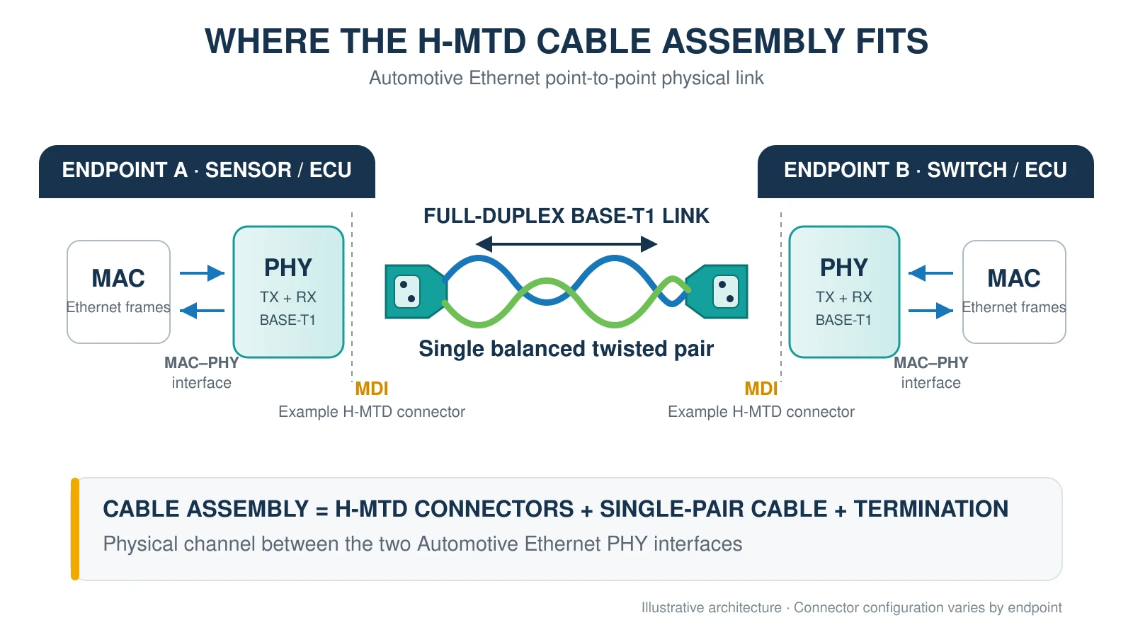
Conventional office Ethernet commonly uses four twisted pairs and an RJ45 connector. Automotive single-pair Ethernet standards such as 100BASE-T1 and 1000BASE-T1 transmit and receive over one balanced pair. The reduced conductor count can help lower cable diameter, harness weight and packaging demand, while Ethernet provides a scalable network for increasingly data-intensive vehicle functions.
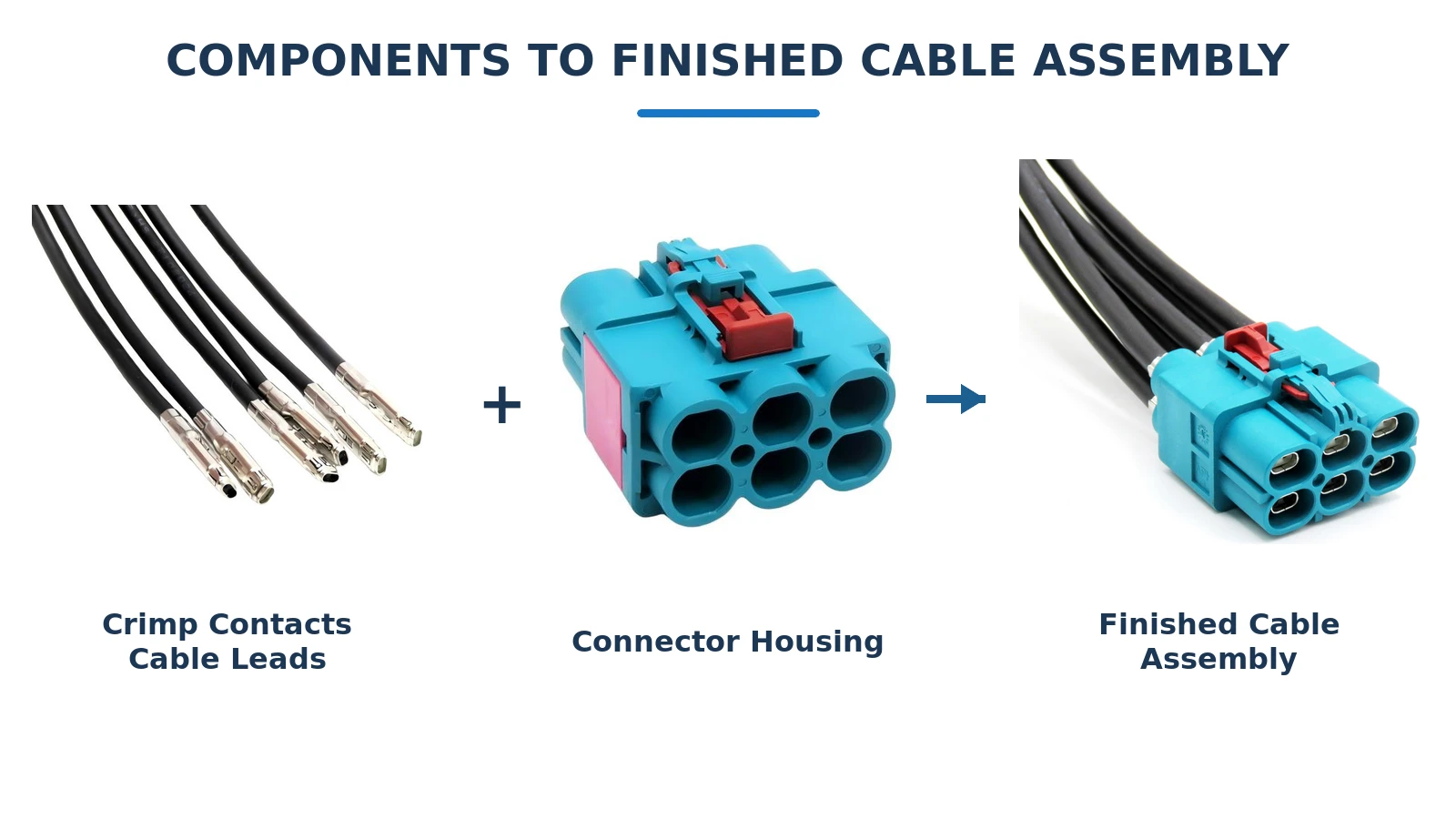
The word assembly matters. A finished automotive Ethernet cable assembly includes the selected cable, contacts, connector housings, shielding and strain-relief features, plus controlled termination at both ends. A good connector attached to the wrong cable—or terminated inconsistently—does not create a compliant channel.
Why engineers are asking about real-world adoption
Engineering discussions repeatedly raise the same questions: Is single-pair Ethernet actually used in production? Is it more expensive? Can it replace CAN? What cabling do modern cameras use? Those questions show mixed informational and commercial intent. Readers first need a clear explanation, but their next step is often component selection, prototyping or sourcing.
Where cable assemblies fit in the vehicle
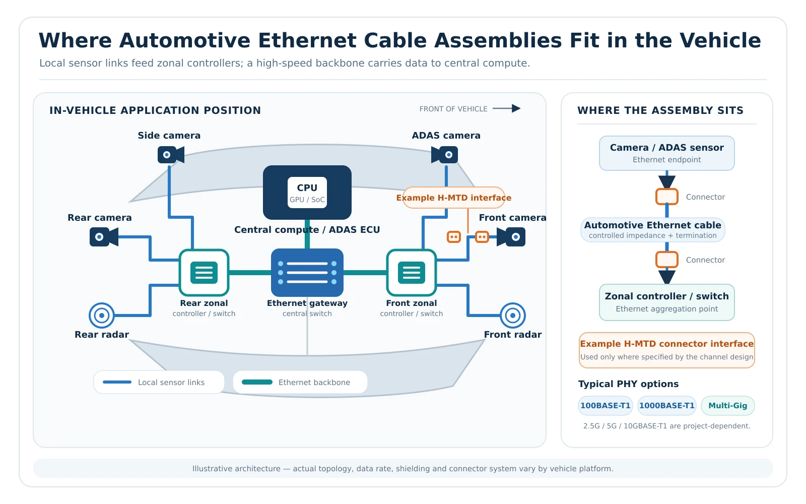
Typical links connect an ECU or Ethernet switch to cameras, radar, LiDAR, displays, gateways and zonal controllers. Development benches also use assemblies between media converters, switches and devices under test. The correct design depends on data rate, link length, EMC environment, mechanical routing and whether the connection must be sealed.
2. Automotive Ethernet Standards and Network Choices
100BASE-T1, 1000BASE-T1 and multi-gig links
| Link option | Nominal data rate | Typical role | Cable-assembly focus |
|---|---|---|---|
| 100BASE-T1 | 100 Mb/s | Control, diagnostics and moderate-bandwidth endpoints | Balanced single pair, channel impedance, EMC and termination quality |
| 1000BASE-T1 | 1 Gb/s | Cameras, gateways, infotainment and higher-throughput ECUs | Tighter channel control, return loss, mode conversion and connector performance |
| 2.5/5/10GBASE-T1 | 2.5–10 Gb/s | High-resolution sensors and backbone links | Higher-frequency cable and connector performance; more demanding validation |
| 10BASE-T1S | 10 Mb/s | Short-reach, lower-speed multidrop networks | Topology and node-count requirements differ from point-to-point T1 links |
IEEE has standardized 100BASE-T1, 1000BASE-T1, multi-gig automotive Ethernet and newer electrical and optical automotive Ethernet work. The practical lesson is simple: “automotive Ethernet” is not one interchangeable cable specification. State the exact PHY standard before selecting an assembly.
Automotive Ethernet complements CAN
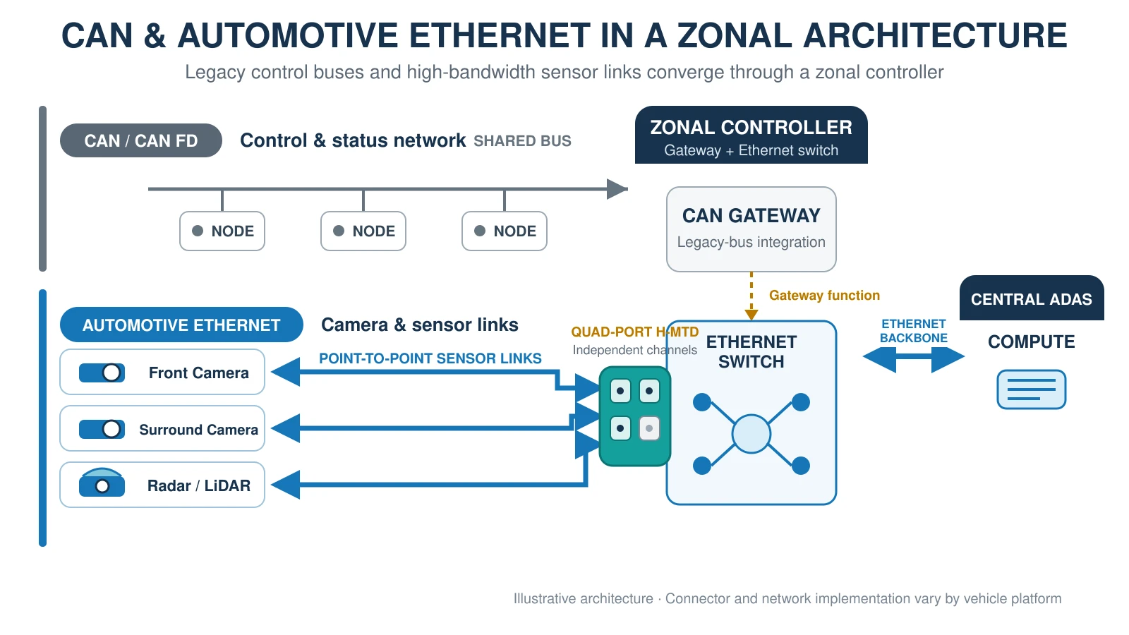
Automotive Ethernet should not be described as a universal replacement for CAN. CAN remains attractive for robust, deterministic, lower-bandwidth control. Ethernet is valuable where bandwidth, IP-based communication, switching or network consolidation matters. Modern architectures can use both, with gateways and domain or zonal controllers separating traffic according to function and safety requirements.
Automotive Ethernet vs. conventional Ethernet vs. CAN
| Feature | Automotive Ethernet | Conventional Ethernet | CAN |
|---|---|---|---|
| Primary strength | High-bandwidth in-vehicle networking | General LAN connectivity | Robust lower-bandwidth control |
| Common cabling | Single balanced pair for T1 standards | Usually four twisted pairs | Twisted pair bus |
| Connector approach | Compact automotive-grade interfaces | Often RJ45 | OEM-specific automotive connectors |
| Topology | Often switched point-to-point; some multidrop options | Switched star | Multidrop bus |
| Selection risk | PHY, EMC and channel mismatch | Category and installation mismatch | Termination, stub and bus-length errors |
3. How to Choose the Cable and Shielding
Match the cable to the PHY and channel
A single pair Ethernet cable must be matched to the electrical requirements of its complete link segment, not selected only by its advertised speed. For example, a 1000BASE-T1 cable assembly requires confirmation of nominal differential impedance, insertion loss, return loss, balance or mode-conversion performance and the permitted link length. The OPEN Alliance TC9 program specifically covers automotive Ethernet cables, connectors, cable assemblies, termination processes and EMC test methods across speed grades.
Choose STP or UTP from the EMC design
Shielded twisted pair (STP) can improve immunity and emissions performance in demanding environments, but the shield must be terminated and grounded correctly. Unshielded twisted pair (UTP) can reduce weight, cost and assembly complexity when the architecture and OEM requirements permit it. Do not assume “shielded is always better”: a poorly terminated shield can undermine the intended EMC strategy.
Include the mechanical environment
Specify temperature range, bend radius, flexing, abrasion, fluids, vibration, retention and sealing needs. Also define routing near high-current conductors, motors, inverters or other noise sources. A laboratory link that passes on a short bench cable may fail after installation if routing and connector transitions were excluded from the channel assessment.
4. Choosing Connectors and H-MTD Interfaces
What H-MTD contributes
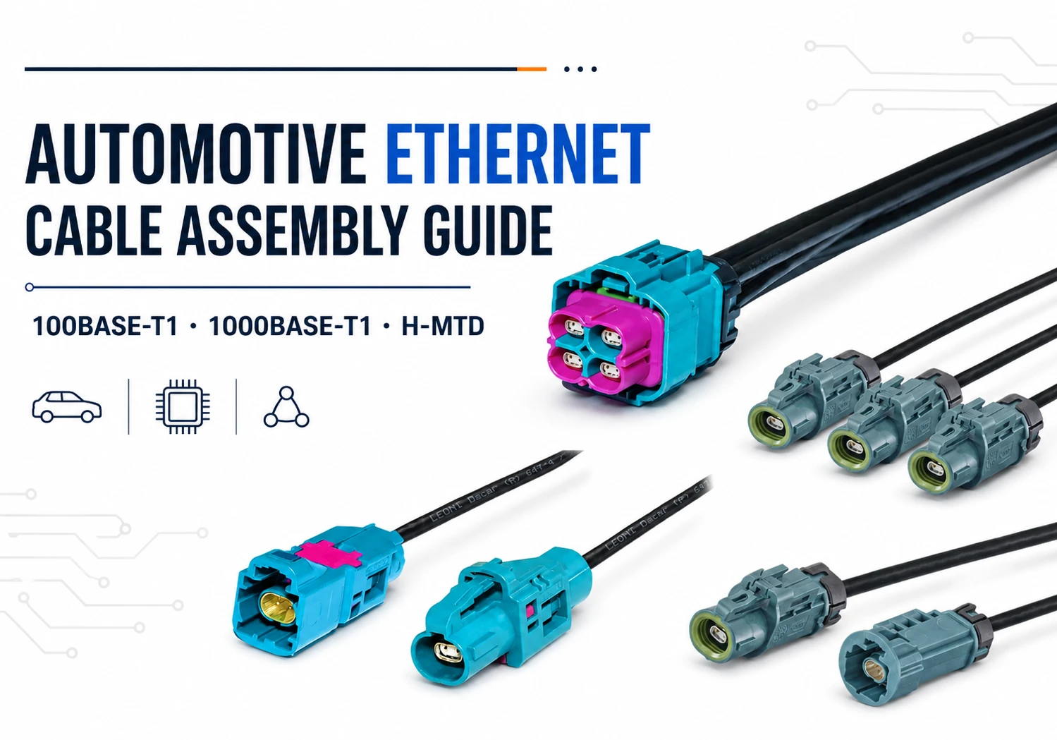
H-MTD is a compact modular differential connector interface used for high-speed vehicle data links. The interface family includes single- and multiport housings and can be paired with shielded, unshielded and other high-performance cable constructions. Published portfolio information covers 100BASE-T1, 1000BASE-T1 and multi-gig Ethernet use cases, as well as additional high-speed protocols.
That does not mean every H-MTD cable assembly automatically supports every published family-level data rate. Performance depends on the exact connector variant, cable, length, termination, PCB transition and full channel validation. Treat “H-MTD” as an interface choice—not a substitute for an electrical specification.
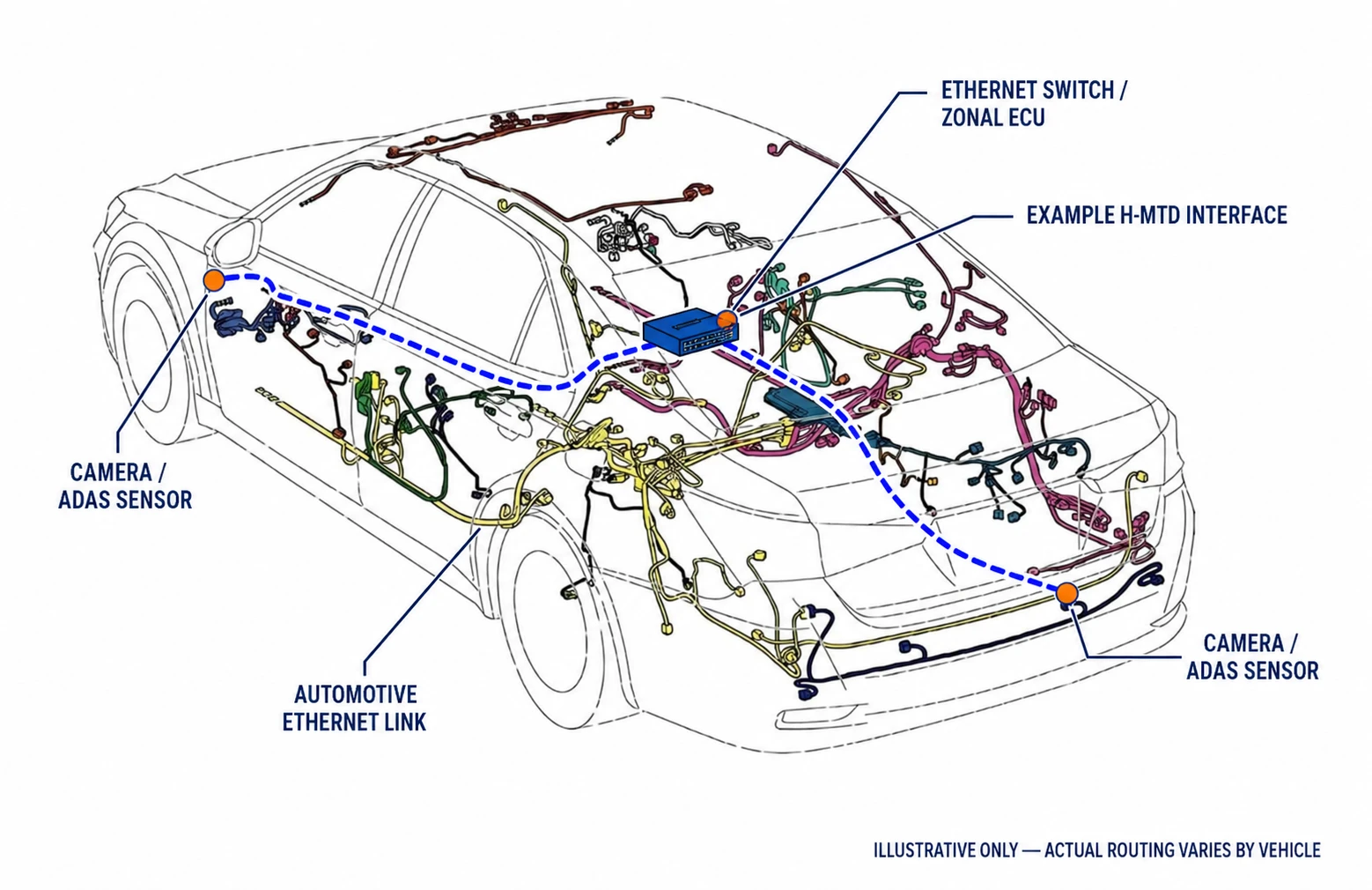
Single-port vs. multiport H-MTD cable assemblies
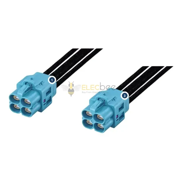
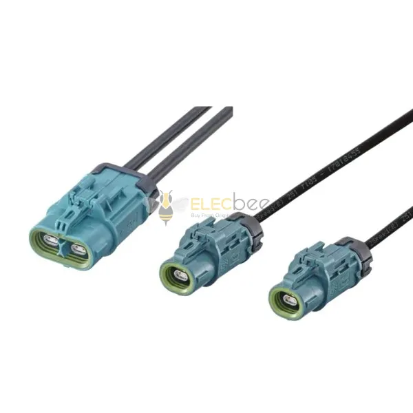
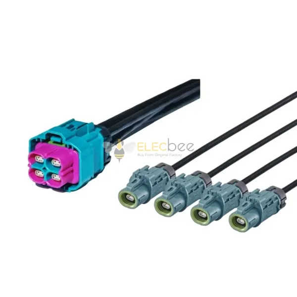
A single-port assembly is useful for one endpoint, a breakout link or a test connection. Dual-, quad- or higher-port configurations can increase packing density at a switch, gateway or ECU. A quad-port housing can simplify mechanical integration for several adjacent channels, but each lane still needs correct coding, routing and channel verification.
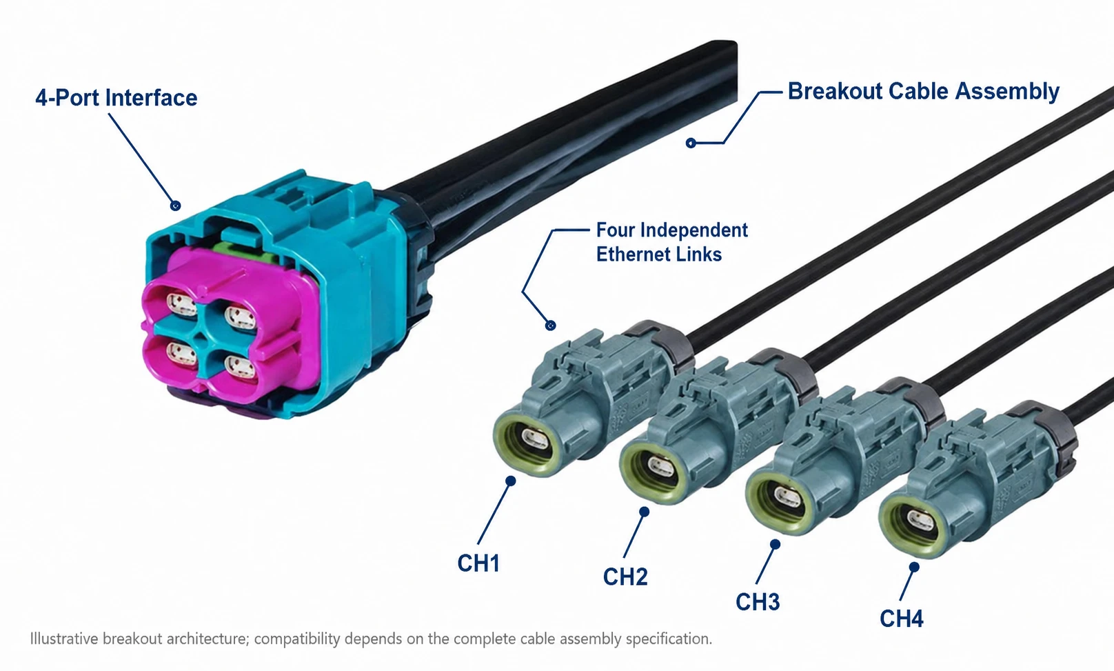
Compatibility must be defined precisely
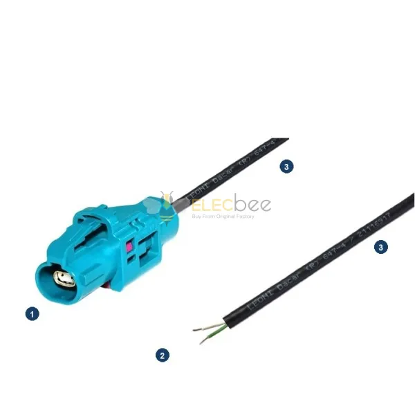
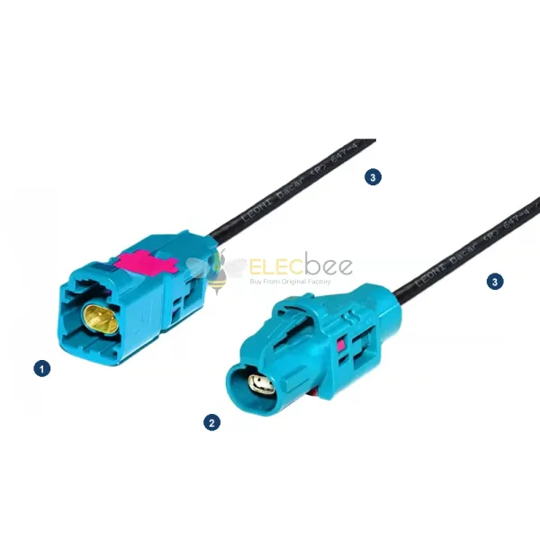
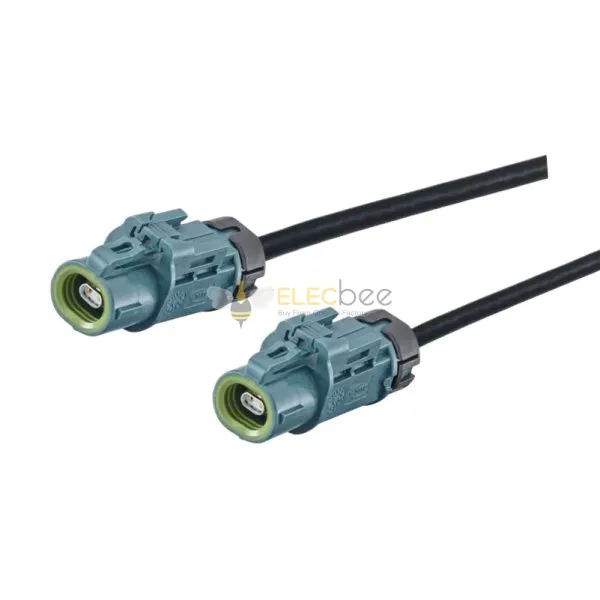
When ordering an H-MTD cable assembly, specify plug or jack, coding, port count, sealed or unsealed construction, mating interface, cable family, length and pinout. “Looks compatible” is not enough. If a third-party assembly is described as H-MTD-compatible, request dimensional, mechanical and electrical evidence appropriate to the intended application.
If you already know a part number—such as an E6K10A- or E6K14D-series reference—verify the complete suffix and controlled drawing. Similar-looking base codes can represent different coding, port, sealing or interface details and should not be treated as interchangeable.
Automotive camera and ADAS links may also use coaxial interfaces, but these are not interchangeable with differential H-MTD systems. See our Mini FAKRA vs FAKRA selection guide to compare their signal structure, coding and typical applications.
5. How to Specify an Automotive Ethernet Cable Assembly
A practical six-step workflow
- Define the endpoint and traffic. Identify the camera, sensor, ECU, switch or converter and calculate required bandwidth with margin.
- Select the PHY standard. State 100BASE-T1, 1000BASE-T1, 2.5/5/10GBASE-T1 or another exact standard.
- Set the channel requirements. Record maximum routed length, impedance, loss limits, topology and any OEM-specific requirements.
- Choose cable construction. Decide STP or UTP, conductor size, jacket, temperature rating, flexibility and environmental resistance.
- Define both connector ends. Specify interface family, plug/jack, coding, port count, orientation, sealing, pinout and strain relief.
- Agree on validation. Define continuity, pinout, TDR/VNA or other channel tests, EMC evidence, mechanical inspection and production traceability.
Information to send with an RFQ
- Application and target vehicle environment
- Required Ethernet standard and data rate
- Connector part numbers or controlled interface drawings
- Plug/jack, coding, single/dual/quad port and sealing requirements
- Cable type, length, tolerance and shielding requirement
- Pinout, labeling and packaging
- Required electrical, mechanical and environmental test reports
Two application scenarios
Scenario 1: Four-camera ECU connection. A central ECU receives four high-bandwidth links. A quad-port H-MTD-compatible interface may reduce connector footprint compared with four separate housings. The engineer still verifies each channel’s protocol, cable length, shielding and insertion/return-loss budget.
Scenario 2: Development-bench extension. A team needs a removable link between a media converter and device under test. The priorities may be known pinout, repeatable mating, controlled cable length and measurement access. A production vehicle assembly may prioritize sealing, vibration resistance and routing constraints instead.
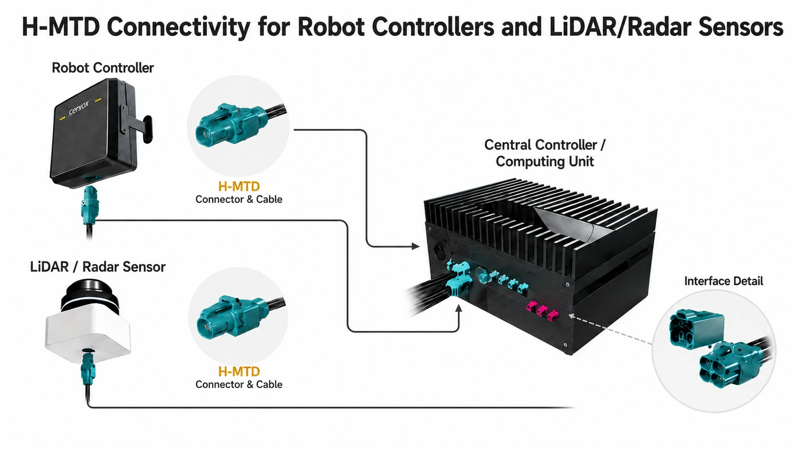
6. Common Mistakes, Validation and Emerging Trends
Common selection mistakes
- Confusing 100BASE-TX with 100BASE-T1
- Assuming an ordinary Cat cable and RJ45 assembly represents an in-vehicle T1 channel
- Selecting by connector name without checking cable and termination performance
- Assuming all H-MTD variants, port counts and codings are interchangeable
- Ignoring shield termination, grounding and PCB transitions
- Claiming Ethernet replaces every CAN function
Validate the complete assembly
Continuity and pinout checks are necessary but insufficient for a high-speed link. Depending on the standard and project, validation may include characteristic impedance, insertion loss, return loss, mode conversion, coupling attenuation, shielding effectiveness, propagation delay and mechanical or environmental tests. The acceptance plan should be agreed before production—not after a link problem appears.
Current automotive Ethernet direction
The standards roadmap is expanding beyond 100 Mb/s and 1 Gb/s links. IEEE’s completed work includes multi-gig electrical automotive Ethernet, greater-than-10-Gb/s electrical automotive Ethernet and multi-gig optical automotive Ethernet. OPEN Alliance TC9 lists active work spanning 1000BASE-T1, 2.5/5/10GBASE-T1 and emerging 25GBASE-T1 channel requirements. This trend increases the importance of treating cable assemblies as engineered channel components rather than commodity jumpers.
7. Automotive Ethernet Cable Assembly FAQ
Is automotive Ethernet the same as normal Ethernet?
No. The Ethernet frame concept is familiar, but automotive T1 PHYs, cabling, connectors, EMC requirements and validation differ from typical office Ethernet.
Does 1000BASE-T1 use one twisted pair?
Yes. 1000BASE-T1 is designed for 1 Gb/s operation over a single balanced twisted pair, with the channel built to its applicable requirements.
Is H-MTD the same as Automotive Ethernet?
No. H-MTD is a connector interface family that can support Automotive Ethernet and other high-speed protocols. The Ethernet standard describes the communication link; the connector is one part of the physical channel.
Should I choose shielded or unshielded cable?
Choose according to the PHY, EMC architecture, routing environment and customer requirements. Both STP and UTP solutions exist, but they have different grounding, weight, cost and validation considerations.
Can Automotive Ethernet replace CAN?
It can replace or consolidate some links, especially where bandwidth is important, but CAN remains useful for many robust lower-bandwidth control functions. The technologies often coexist.
What should I verify before ordering an H-MTD cable assembly?
Confirm the exact interface variant, coding, plug/jack gender, port count, pinout, cable type, length, shielding, sealing, required data rate and test evidence.