

 0


M8 · Field-wireable connectors
M8 screw-terminal connectors
Choose the fit.
Wire it on site.
Build a cable connection to suit your installation. Screw terminals connect the conductors without soldering, while straight and right-angle housings give you a choice of cable routing.
- 3 & 4Contact options
- Male & femaleMating faces
- A-codedM8 × 1 coupling
- UnshieldedFamily shown here
Housing & fit
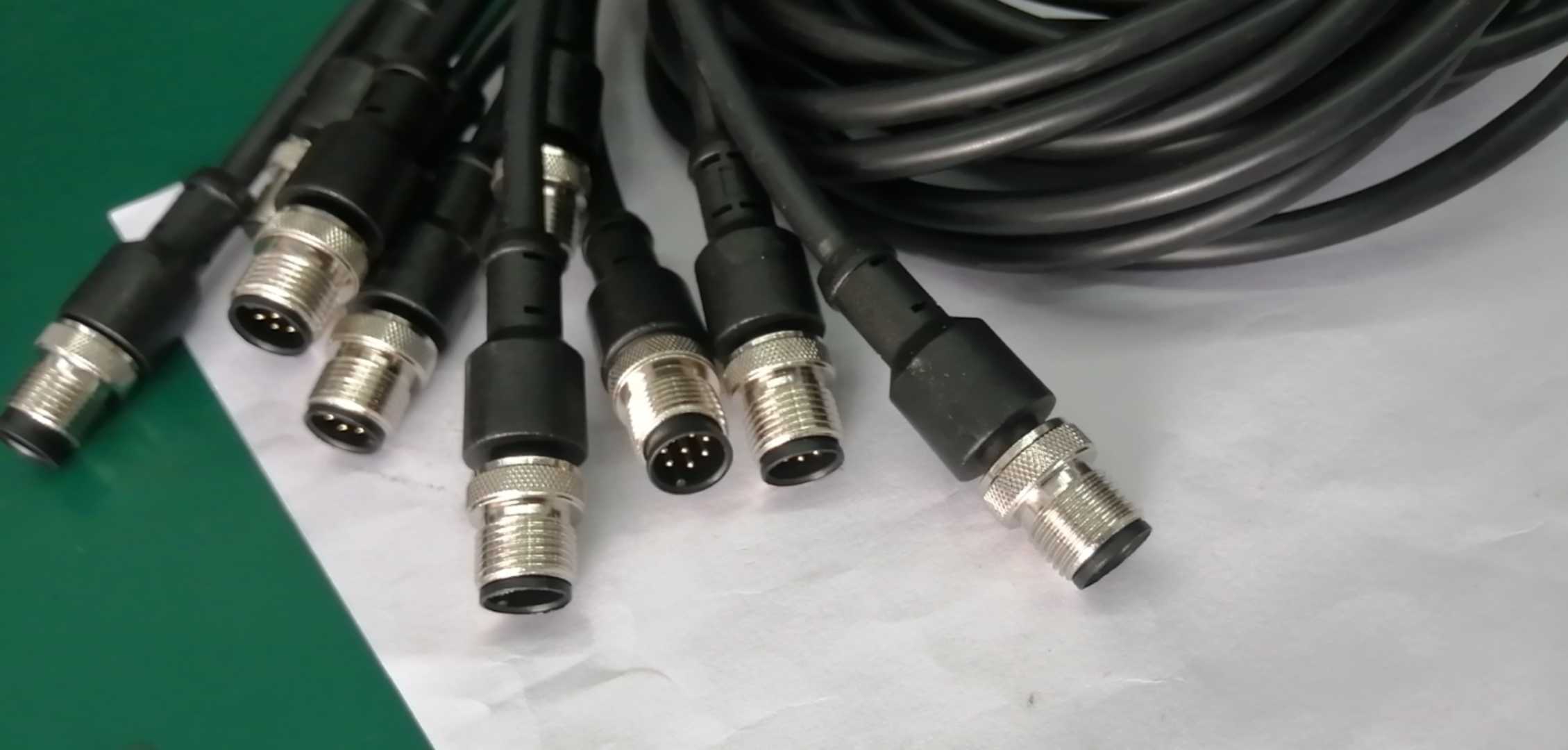
Four housing options
Choose the mating face, then the cable exit. The outlines below apply to the illustrated 3- and 4-contact housing families.
Straight male
3 / 4 contacts

Rear cable exit
Approx. 49 mm along mating axis
Straight female
3 / 4 contacts

Rear cable exit
Approx. 44 mm along mating axis
Right-angle male
3 / 4 contacts

90° cable exit
Approx. 37.5 mm along mating axis
Right-angle female
3 / 4 contacts

90° cable exit
Approx. 32.2 mm along mating axis
Dimensions in millimetres. Product photos show representative 3-contact versions. The selected product determines the supplied contact count and housing style.
Materials & construction
Inside the connection
Gold-plated brass contacts sit in an insulating insert. A nickel-plated brass coupling nut joins the mating thread, and the rear cable entry grips the jacket.


- Gold-plated brass contacts
- Screw terminals secure the individual conductors to the contacts.
- PA66 housing & insulating insert
- The body encloses the terminals; the insert keeps the contacts in their defined positions.
- Nickel-plated brass coupling nut
- The threaded M8 × 1 interface secures the mated connection.
- NBR seal & rear cable grip
- The seal, pinch ring and pressing screw fit around the cable jacket. Select the cable outside diameter for the exact part.
Contacts & electrical data
Match the face, then the numbers
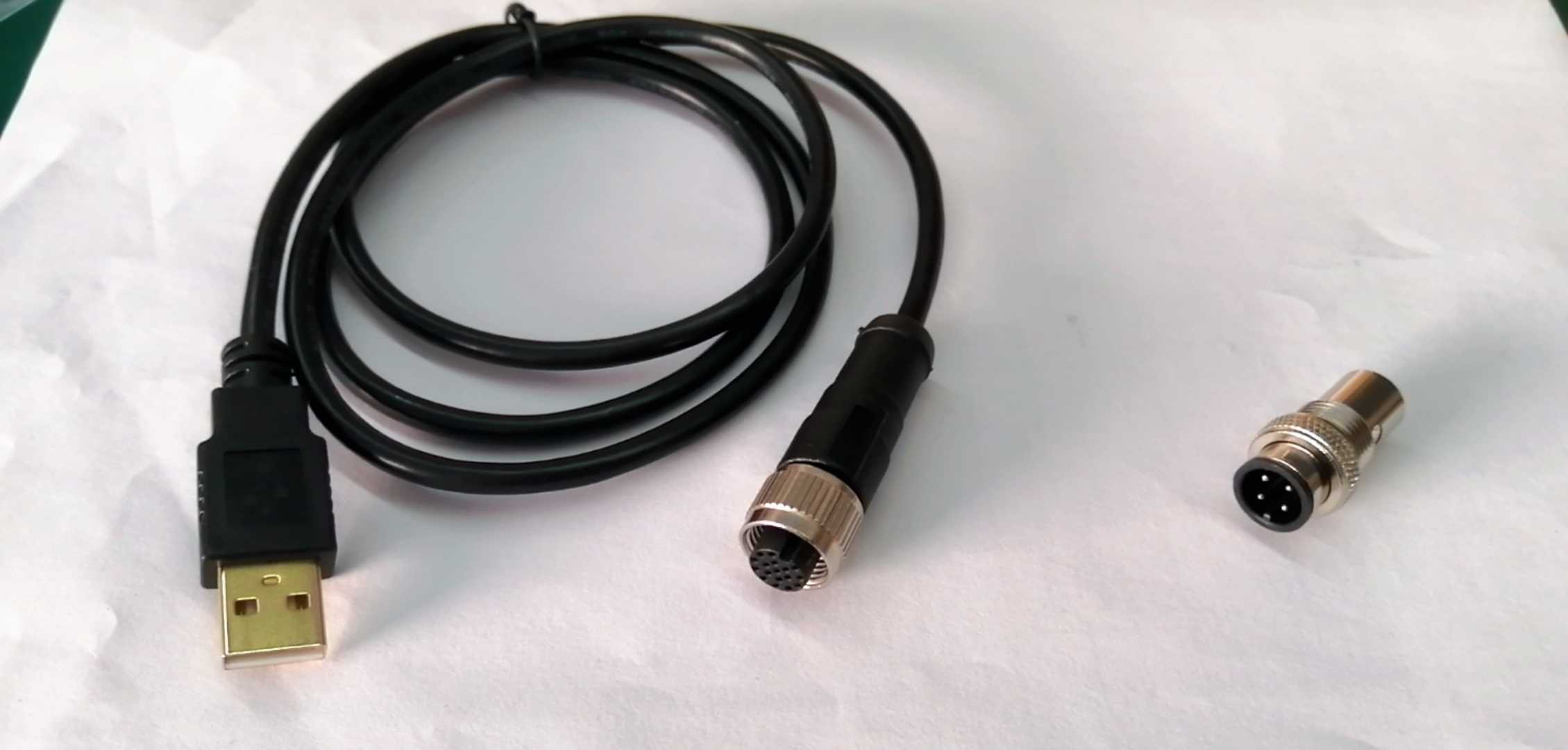
Views below look into the mating face. Male and female layouts are shown separately and apply to the straight and right-angle versions in this family.
3 contacts
A-coded

4 contacts
A-coded

Contact numbers identify positions. Use the connected equipment’s wiring diagram for signal assignments.
- Insulation resistance
- ≥ 100 MΩ
- Contact resistance
- ≤ 5 mΩ
- Protection rating
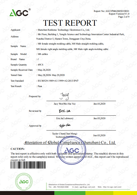
- IP67 when mated
- Mating cycles
- ≥ 500
Electrical data above apply to both the 3- and 4-contact unshielded A-coded screw-terminal versions shown.
Before you connect
Complete the match
Mating face
Match A coding, contact count and male / female orientation to the device or mating cable.
Cable & clearance
Check the selected part’s cable diameter range and dimensions. Allow room for the cable exit and bend.
Wiring & sealing
Follow the contact numbers and equipment wiring diagram. IP67 applies to the mated connection.