L298N L298P 4A Dual Channel Motor Driver Module Motor Shield R3
- Working Voltage: 5V ~ 12V
- Motor controller: L298P, drives 2 DC motors or 1 stepper motor
- Max current: 2A per channel or 4A max (with external power supply)
- Current sensing: 1.65V/A
- Free running stop and brake function
About power:
The Motor Shield must be powered only by an external power supply. Because the L298 IC mounted on the shield has two separate power connections, one for the logic and one for the motor supply driver. The required motor current often exceeds the maximum USB current rating.
External (non-USB) power can come either from an AC-to-DC adapter (wall-wart) or battery. The adapter can be connected by plugging a 2.1mm center-positive plug into the 's board power jack on which the motor shield is mounted or by connecting the wires that lead the power supply to the Vin and GND screw terminals, taking care to respect the polarities.
To avoid possible damage to the board on which the shield is mounted, we recommend using an external power supply that provides a voltage between 7 and 12V. If your motor require more than 9V we recommend that you separate the power cable of the shield and the board on which the shield is mounted. This is possible by cutting the "Vin Connect" jumper placed on the back side of the shield. The absolute limit for the Vin at the screw terminals is 18V.
The power pins are as follows:
Vin on the screw terminal block, is the input voltage to the motor connected to the shield. An external power supply connected to this pin also provide power to the board on which is mounted. By cutting the "Vin Connect"jumper you make this a dedicated power cable for the motor.
GND Ground on the screw terminal block.
The shield can supply 2 amperes per channel, for a total of 4 amperes maximum.
About input and output:
This shield has two separate channels, called A and B, that each use 4 of the pins to drive or sense the motor. In total there are 8 pins in use on this shield. You can use each channel separately to drive two DC motors or combine them to drive one unipolar stepper motor.
The shield's pins, divided by channel are shown in the table below:
Function | pins per Ch. A | pins per Ch. B |
Direction | D12 | D13 |
PWM | D3 | D11 |
Brake | D9 | D8 |
Current Sensing | A0 | A1 |
If you don't need the Brake and the Current Sensing and you also need more pins for your application you can disable this features by cutting the respective jumpers on the back side of the shield.
The additional sockets on the shield are described as follow:
Screw terminal to connect the motors and their power supply.
2 TinkerKit connectors for two Analog Inputs (in white), connected to A2 and A3.
2 TinkerKit connectors for two Aanlog Outputs (in orange in the middle), connected to PWM outputs on pins D5 and D6.
2 TinkerKit connectors for the TWI interface (in white with 4 pins), one for input and the other one for output.
Motors connections:
Brushed DC motor. You can drive two Brushed DC motors by connecting the two wires of each one in the (+) and (-) screw terminals for each channel A and B. In this way you can control its direction by setting HIGH or LOW the DIR Aand DIR B pins, you can control the speed by varying the PWM A and PWM B duty cycle values. The Brake A andBrake B pins, if set HIGH, will effectively brake the DC motors rather than let them slow down by cutting the power. You can measure the current going through the DC motor by reading the SNS0 and SNS1 pins. On each channel will be a voltage proportional to the measured current, which can be read as a normal analog input, through the function analogRead() on the analog input A0 and A1. For your convenience it is calibrated to be 3.3V when the channel is delivering its maximum possible current, that is 2A.
Contact Sales
Your Name* | |
Your Email* | |
Topic* | |
Qty | |
Message | |
SUBMIT |
- Description
1 x Motor Driver Module
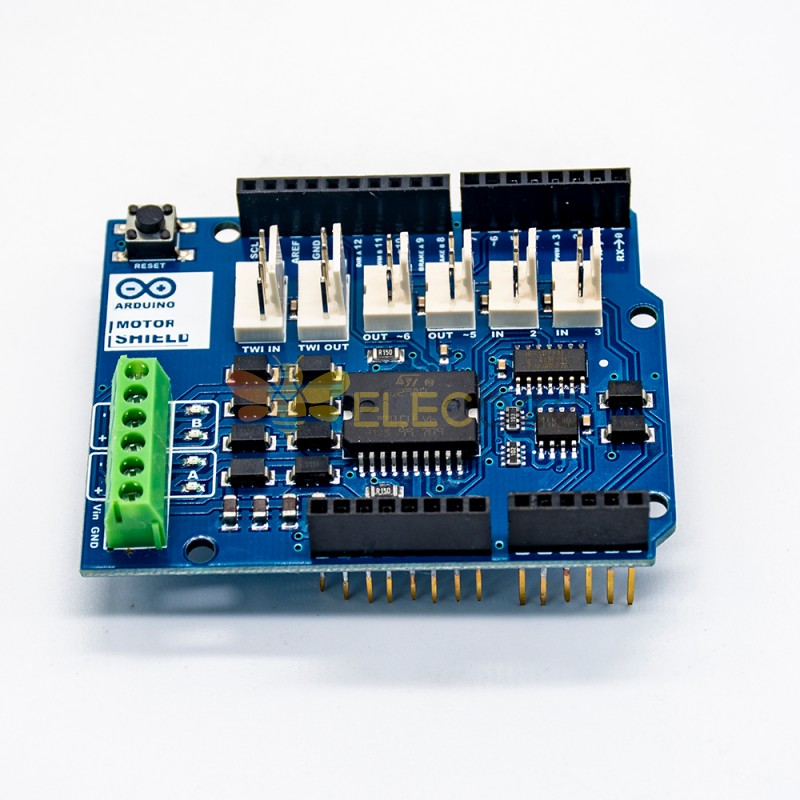
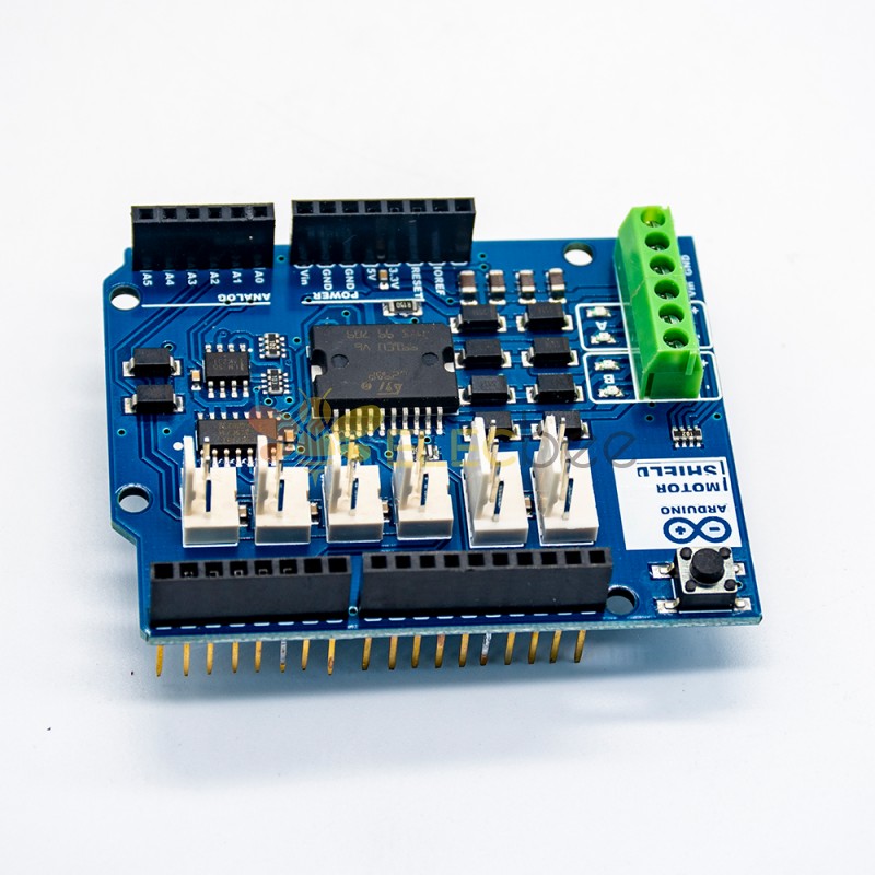
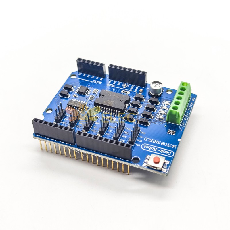
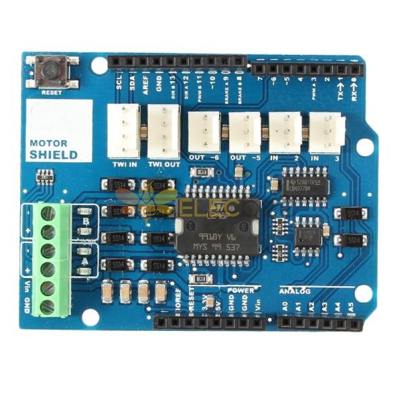
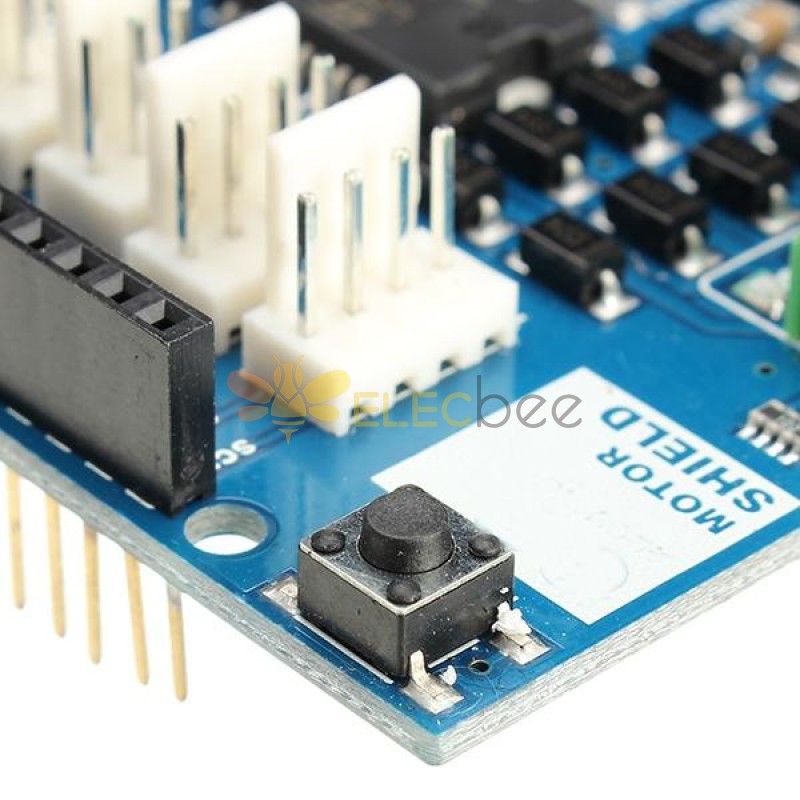
L298N L298P 4A Dual Channel Motor Driver Module Motor Shield R3 For
Description:
The Motor Shield is based on the L298, which is a dual full-bridge driver designed to drive inductive loads such as relays, solenoids, DC and stepping motors. It lets you drive two DC motors with your board, controlling the speed and direction of each one independently. You can also measure the motor current absorption of each motor, among other features. The shield is TinkerKit compatible, which means you can quickly create projects by plugging TinkerKit modules to the board.
1 x Motor Driver Module
- Reviews (29)
- All(29)
- Q & A
-
: Where is the origin of Elecbee products? Are they certificated?2023-03-03
-
Answer:
Elecbee has long-term cooperation agreements with the OEM factories in China. So that we are able to reduce the intermediate channel cost, and help you save money. Our products are all made strictly according to the relative global standard, to ensure the products have good compatibility and excellent quality.
2023-03-03
-
: What forms of payment do you accept?2023-03-03
-
Answer:
Our main payment methods include Paypal, Credit Cards, Debit Cards, Bank Transfer, and more to discover. Please choose the payment methods in your favor.
2023-03-03
-
: When will you arrange shipment?2023-03-03
-
Answer:
After confirming receipt of your payment. We will arrange the delivery as soon as possible and upload the courier number to the website for you to track.
2023-03-03
-
: How to exchange or return?2023-03-03
-
Answer:
1. You can apply to return within 30 days after receipt of the goods. Please make sure the outside package is intact, and the product is in its original condition. We will arrange your refund according to the relevant provisions once the package is received.
2. Return process: You Apply for a Return - Approve the Return - Arrange a Return - Receive the Products and make Inspection - We arrange a Refund;
3. We will bear the freight charges for returns caused by us, for instance, the quality problem. As to returns caused by the buyer, the buyer should be responsible for the shipping fee.
2023-03-03
Related Products
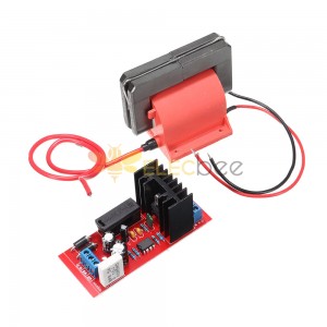
30000V High Power 12V High Voltage Inverter Packet Driving Board Laser Packet Inverter Board
1 x 30000V High Power 12V High Voltage Inverter..
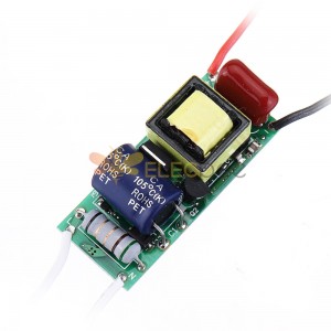
7W 9W 12W 15W 7-15W LED Driver Input AC 85-265V Power Supply Built-in Drive Power Supply 260-280mA Lighting
Specifications:Input voltage: AC 85-265VOutput voltage: DC21-54VOutput current: 260-280m(adjusta..
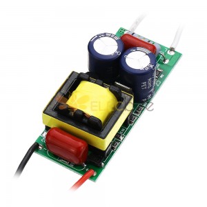
5pcs 15-24W LED Driver Input AC90-265V to DC45-82V Built-in Drive Power Supply Adjustable Lighting for DIY LED Lamps
Specifications: Input voltage: AC90-265VOutput voltage: DC45-82VOutput current: 280-300mA(adjustabl..
3pcs 6W 7W LED Non Isolated Modulation Light External Driver Power Supply AC110/220V Module
Specifications:Input voltage: AC90-265VOutput voltage: DC18-24VOutput current: 280-300mA(adjustabl..