
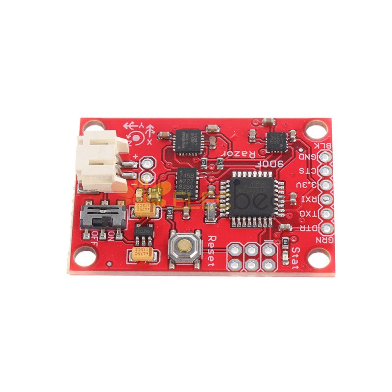
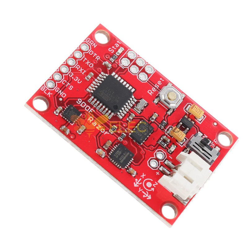


- Description


Standard calibration:
It might be good to power up the Razor a few minutes before calibration, so the sensors can warm up. Calibrating the sensors the first time can be a little tricky, but let’s go:
- Open for /Razor_AHRS/Razor_AHRS.ino using for and find the section "USER SETUP AREA" / "SENSOR CALIBRATION". This is where you put the calibration values later.
- Connect the Razor AHRS to your computer, set the correct serial port in for and open the Serial Monitor.
If you didn’t change the firmware defaults, you should see lots of output like this:
#YPR=-155.73,-76.48,-129.51Set the firmware output mode to calibration by sending the string #oc. You should now see output like this:
accel x,y,z (min/max) = -5.00/-1.00 25.00/29.00 225.00/232.00
- Calibrating the accelerometer:
- We'll try to find the mini mum and maximum output values for the earth gravitation on each axis. When you move the board, move it real slowly, so the acceleration you apply to it is as small as possible. We only want pure gra vity!
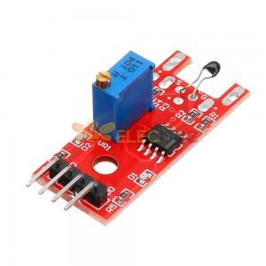
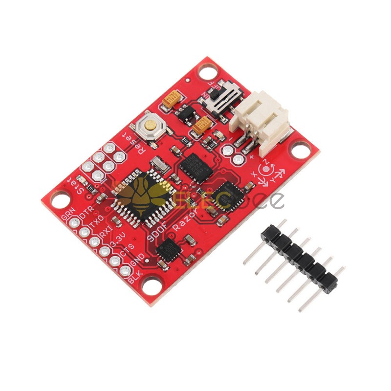
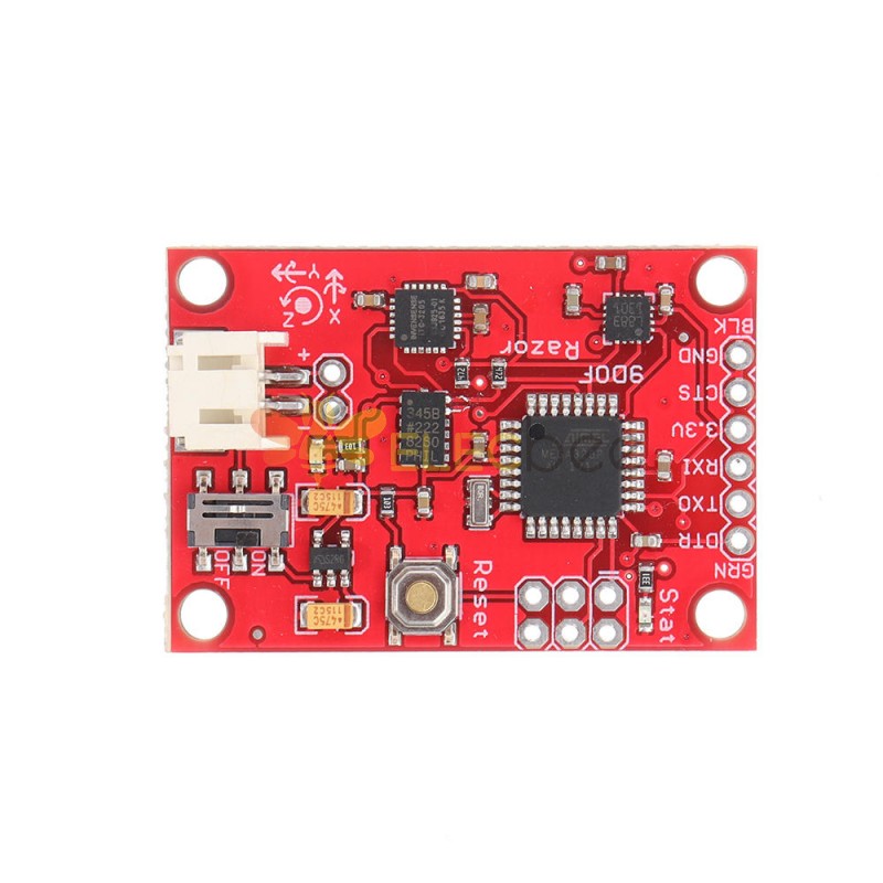
- Take the board and point straight down with the x-axis (remember: x-axis = towards the short edge with the connector holes). While you do that, you can see the x-maximum (the second value) getting bigger.
- Hold the board very still and reset the measurement by sending #oc again.
- Now carefully tilt the board a little in every direction until the value does not get bigger any more and write down the x-maximum value.
- Do the same thing for the opposite side (x-axis pointing up) to get the x-mini mum: bring into position, send #oc to reset measurement, find x-mini mum value and write it down.
- Do the same thing for the z-axis (down and up) and the y-axis (right and left).
- If you think you messed up the measurement by shaking or moving the board too fast, you can always reset by sending #oc.
- You should now have all the min/max values. Put them into Razor_AHRS.ino.
- NOTE: You have to be really careful when doing this! Even slightly tapping the board with the finger messes up the measurement (try it!) and leads to wrong calibration. Use #oc very often and double check your min/max values)
Calibrating the magnetometer:
- This time you can shake the board as much as you want, but move it away from magnetic distortions introduced by computers and other electronic devices and metal objects.
- We’re still calibration mode for the accelerometer. Send #on, which will move calibration to the next sensor, which is the magnetometer.
- NOTE: This section stays here for reference, but you should use the newer "Extended magnetometer calibration (see next section) as it yields much better results! You can ski p this and continue with the gyroscope.
- We'll try to find the mini mum and maximum output values for the earth magnetic field on each axis. This basically works like calibrating the accelerometer, except the magnetic field of the earth does not point down straight. Depending on where on the planet you currently are, it points north-and-up (southern hemisphere) or north-and-down (northern hemisphere) at a certain angle. This angle is called inclination. Additionally there might be a tiny deviation from true geo graphic north, which is called declination. SeeWikipedia. The following description assumes you’re calibrating the magnetometer on the northern hemisphere.
- Hold the board flat like a compass with the x-axis (remember: x-axis = forward, towards the connector holes) pointing north. Then begin to rotate the board around the east-west axis so it starts pointing down. Observe the x-maximum (the second value) in theSerial Monitor and you will notice when you aligned the board’s x-axis with the magnetic field of the earth. Stop rotating there and again tilt a little in every direction until the value does not get bigger any more.
- Do the same thing for the opposite side to get the x-mini mum: first point north, then down.
- For the magnetometer we don’t need to reset with #oc between measurements.
- Do the same thing for the z-axis (up/down) and the y-axis (left/right).
- NOTE: The rotation of the board around the axis you want to measure doesn’t matter, only that it points into the correct direction. E.g when you start measuring the z-axis, it doesn’t matter if the x-axis points up or down or left or right.
You should now have something like this in your Serial Monitor:
magn x,y,z (min/max) = -564.00/656.00 -585.00/635.00 -550.00/564.00Put these values into Razor_AHRS.ino.
Calibrating the gyroscope:
- Lay the Razor still on the table.
- We’re still calibration mode for the magnetometer. Send #on, which will move calibration to the next sensor, which is the gyroscope.
- Wait for 10 seconds, and do not move the Razor. It will collect and average the noise of the gyroscope on all three axes.
You should now have output that looks like this:
gyro x,y,z (current/average) = -29.00/-27.98 102.00/100.51 -5.00/-5.85- If you think you messed up the measurement by shaking or moving the board, you can reset by sending #oc.
- Take the second values of each pair and put them into Razor_AHRS.ino.
- Done :)
Extended magnetometer calibration
- To start calibrating, put the sensor in the magnetic environment where it will be used later - e.g. in the exact spot on your headphones, if you need to to head-tracking for audio applications (headphones have strong magnets, the less you move the sensor after calibrating, the better your results will be; you should also think about putting some dummy material between the ear cups to bring them in normal hearing position).
- Quit all applications that read from the sensor (e.g. Serial Monitor, Processing test sketch, …) and run the Processing magnetometer calibration sketch located in in Processing/Magnetometer_calibration. In fact, you have to install the EJML library first, else the sketch won’t run. How to do that? Have a look at the NOTE at the top of Magnetometer_calibration.pde.
Try to rotate the sensor in a way so that you cover all orientations so you produce dots that more or less evenly cover the sphere.
In a mostly undistorted environment this could look something like this:

Hit SPACE and watch the Processing console - you’ll find some lines of code that you have to put into the firmware under "USER SETUP AREA" / "SENSOR CALIBRATION" and you’re done.
The collected data (the dots) are also written to a file magnetom.float in the sketch folder. Now in case you own Matlab, underMatlab/magnetometer_calibration you’ll find a script called magnetometer_calibration.m that uses this file and produces some plots for you, so you can visually check the calibration.
Ellipsoid fit and corrected values:


Another calibration example: Soft iron gives a sphere scaled and distorted into an ellipsoid.
Sampled raw magnetometer values:

Ellipsoid fit and corrected values:


- Reviews (29)
- Q & A
-
: Where is the origin of Elecbee products? Are they certificated?2023-03-03
-
Answer:
Elecbee has long-term cooperation agreements with the OEM factories in China. So that we are able to reduce the intermediate channel cost, and help you save money. Our products are all made strictly according to the relative global standard, to ensure the products have good compatibility and excellent quality.
2023-03-03
-
: What forms of payment do you accept?2023-03-03
-
Answer:
Our main payment methods include Paypal, Credit Cards, Debit Cards, Bank Transfer, and more to discover. Please choose the payment methods in your favor.
2023-03-03
-
: When will you arrange shipment?2023-03-03
-
Answer:
After confirming receipt of your payment. We will arrange the delivery as soon as possible and upload the courier number to the website for you to track.
2023-03-03
-
: How to exchange or return?2023-03-03
-
Answer:
1. You can apply to return within 30 days after receipt of the goods. Please make sure the outside package is intact, and the product is in its original condition. We will arrange your refund according to the relevant provisions once the package is received.
2. Return process: You Apply for a Return - Approve the Return - Arrange a Return - Receive the Products and make Inspection - We arrange a Refund;
3. We will bear the freight charges for returns caused by us, for instance, the quality problem. As to returns caused by the buyer, the buyer should be responsible for the shipping fee.
2023-03-03
Related Products
MH-Z19B Upgrade Version 0-5000PPM Infrared CO2 Sensor For CO2 Indoor Air Quality Monitor UART/PWM
20pcs APDS-9960 Gesture Sensor Module Digital RGB Light Sensor for Arduino