


- Description
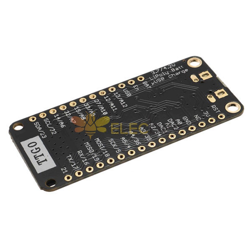
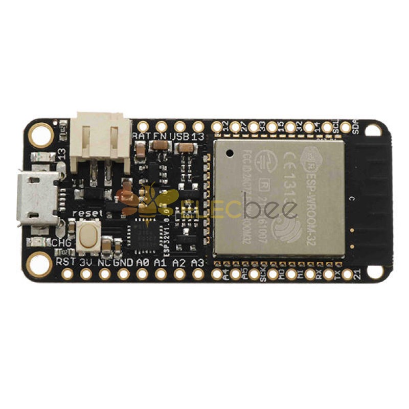
Power Pins: Power Pins:
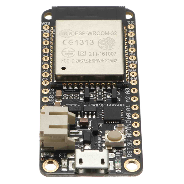
GND - this is the common ground for all power and logic
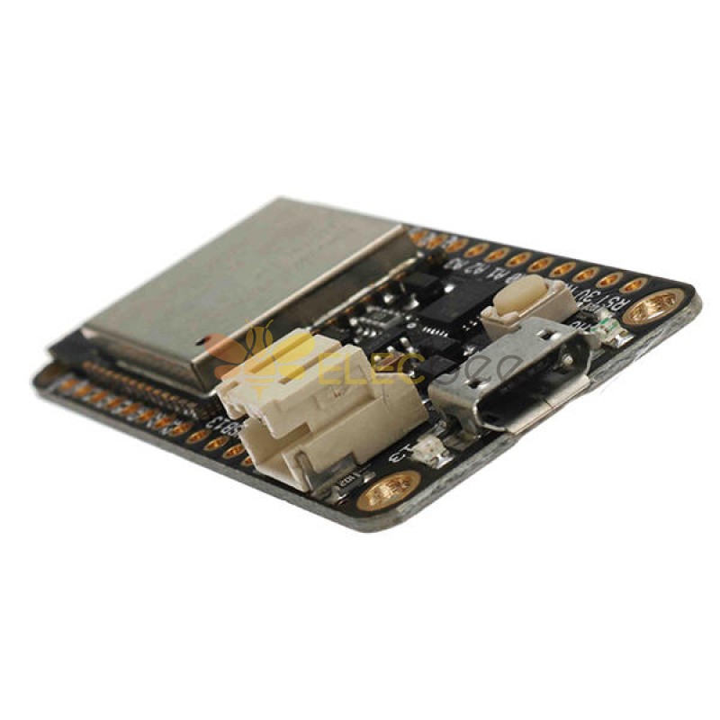
BAT - this is the positive voltage to/from the JST jack for the optional Lipoly battery
USB - this is the positive voltage to/from the micro USB jack if connected
EN - this is the 3.3V regulator's enable pin. It's pulled up, so connect to ground to disable the 3.3V regulator
3V - this is the output from the 3.3V regulator. The regulator can supply 500mA peak but half of that is drawn by the ESP32, and it's a fairly power-hungry chip. So if you need a ton of power for stuff like LEDs, motors, etc. Use the USB or BAT pins, and an additional regulator
Logic pins:
This is the general purpose I/O pin set for the microcontroller. All logic is 3.3V
The ESP32 runs on 3.3V power and logic, and unless otherwise specified, GPIO pins are not 5V safe!
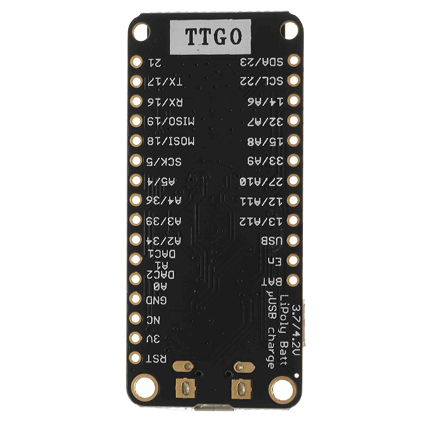
Serial pins:
RX and TX are the additional Serial1 pins, and are not connected to the USB/Serial converter. That means you can use them to connect to UART-devices like GPS's, fingerprint sensors, etc.
The TX pin is the output from the module. The RX pin is the input into the module. Both are 3.3V logic
I2C & SPI pins:
You can use the ESP32 to control I2C and SPI devices, sensors, outputs, etc. If using with , the standard Wire and SPI devices work as you'd expect!
Note that the I2C pins do not have pullup resistors already! You must add them if you want to communicate with an I2C device
GPIO & Analog Pins:
There are tons of GPIO and analog inputs available to you for connecting LEDs, buttons, switches, sensors, etc. Here's the remaining pins available.
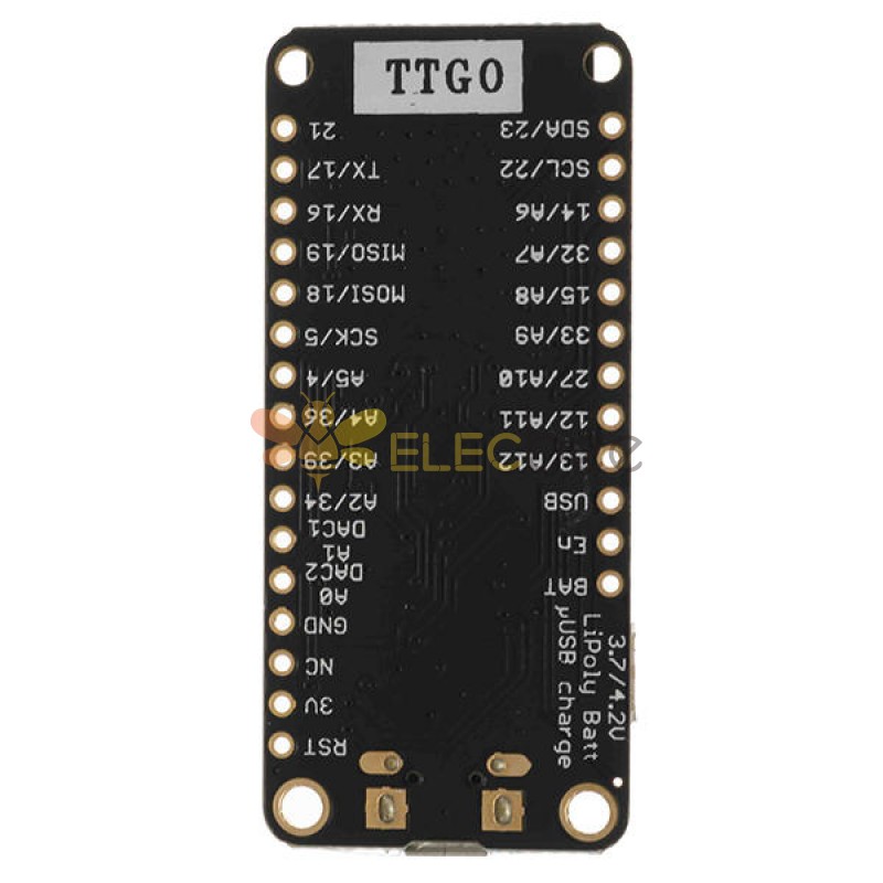
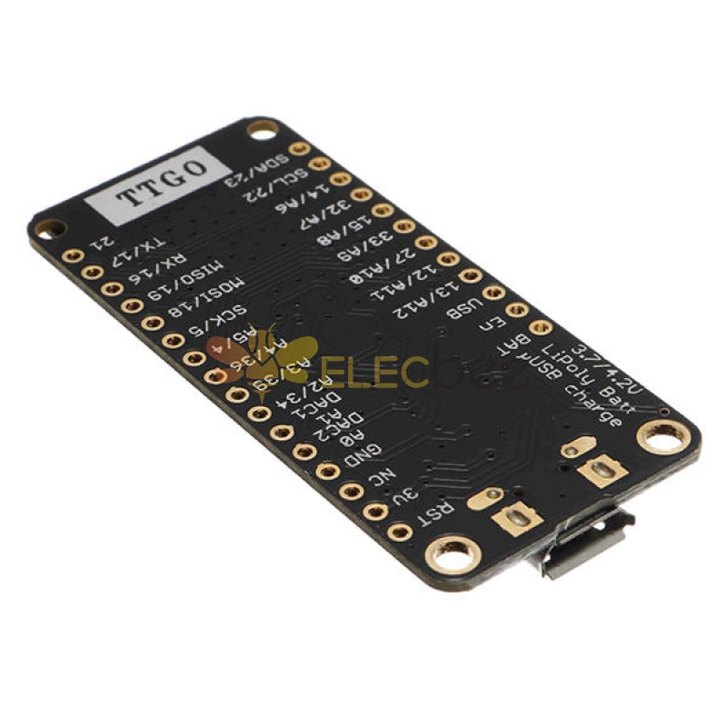
Bottom row:
A0 - this is an analog input A0 and also an analog output DAC2. It can also be used as a GPIO #26
A1 - this is an analog input A1 and also an analog output DAC1. It can also be used as a GPIO #25
A2 - this is an analog input A2 and also GPI #34. Note it is not an output-capable pin!
A3 - this is an analog input A3 and also GPI #39. Note it is not an output-capable pin!
A4 - this is an analog input A4 and also GPIO #36
A5 - this is an analog input A5 and also GPIO #4
21 - General purpose IO pin #21
Top row:
13 - This is GPIO #13 and also an analog input A12. It's also connected to the red LED next to the USB portIt's also connected to the red LED next to the USB port
12 - This is GPIO #12 and also an analog input A11. This pin has a pull-down resistor built into it, we recommend using it as an output only, or making sure that the pull-down is not affected during boot.
27 - This is GPIO #27 and also an analog input A10
33 - This is GPIO #33 and also an analog input A9. It can also be used to connect a 32 KHz crystal.
15 - This is GPIO #15 and also an analog input A8
32 - This is GPIO #32 and also an analog input A7. It can also be used to connect a 32 KHz crystal.
14 - This is GPIO #15 and also an analog input A6
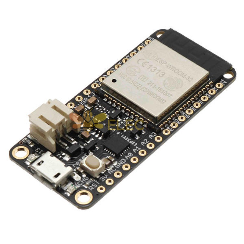
Here are:
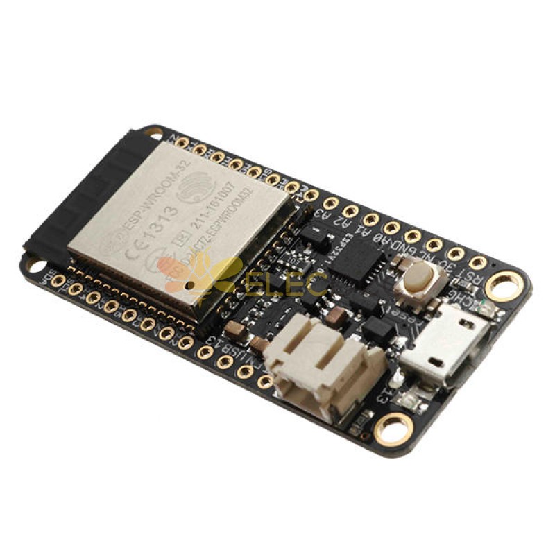
240 MHz dual core Tensilica LX6 microcontroller with 600 DMIPS
Integrated 520 KB SRAM
Integrated 802.11b/g/n HT40 Wi-Fi transceiver, baseband, stack and LWIP
Integrated dual mode bluetooth (classic and BLE)
4 MByte flash
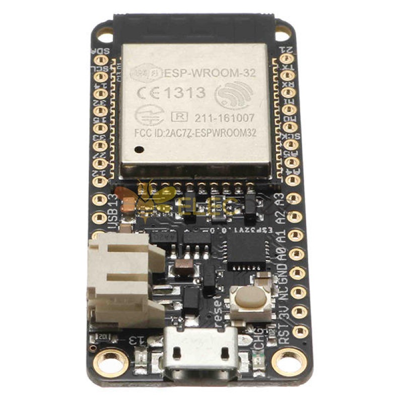
On-board PCB antenna
Ultra-low noise analog amplifier
Hall sensor
10x capacitive touch interface
32 kHz crystal oscillator
3 x UARTs (only two are configured by default in the Feather IDE support, one UART is used for bootloading/debug)
2 x I2C (only one is configured by default in the Feather IDE support)
12 x ADC input channels
2 x I2S Audio
2 x DAC
PWM/timer input/output available on every GPIO pin
OpenOCD debug interface with 32 kB TRAX buffer
SDIO master/slave 50 MHz
SD-card interface support
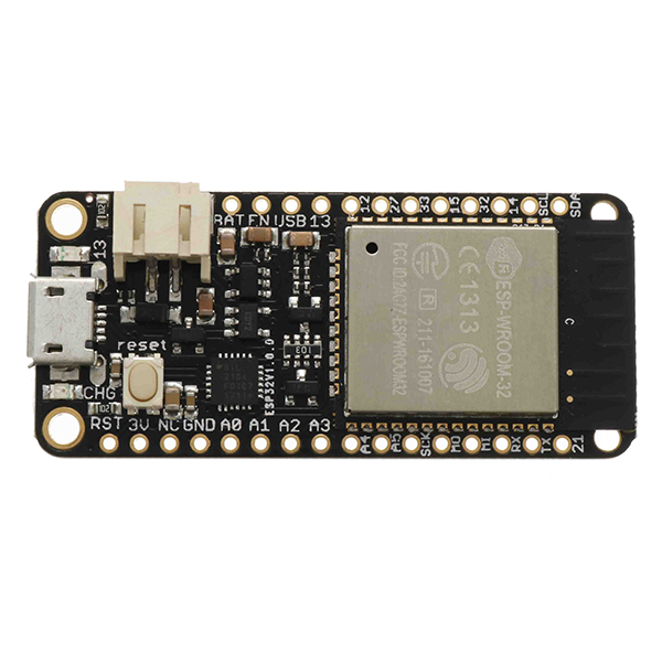
GND - this is the common ground for all power and logic
BAT - this is the positive voltage to/from the JST jack for the optional Lipoly battery
USB - this is the positive voltage to/from the micro USB jack if connected
EN - this is the 3.3V regulator's enable pin. It's pulled up, so connect to ground to disable the 3.3V regulator
3V - this is the output from the 3.3V regulator. The regulator can supply 500mA peak but half of that is drawn by the ESP32, and it's a fairly power-hungry chip. So if you need a ton of power for stuff like LEDs, motors, etc. Use the USB or BAT pins, and an additional regulator
Logic pins:
This is the general purpose I/O pin set for the microcontroller. All logic is 3.3V
The ESP32 runs on 3.3V power and logic, and unless otherwise specified, GPIO pins are not 5V safe!
Serial pins:
RX and TX are the additional Serial1 pins, and are not connected to the USB/Serial converter. That means you can use them to connect to UART-devices like GPS's, fingerprint sensors, etc.
The TX pin is the output from the module. The RX pin is the input into the module. Both are 3.3V logic
I2C & SPI pins:
You can use the ESP32 to control I2C and SPI devices, sensors, outputs, etc. If using with , the standard Wire and SPI devices work as you'd expect!
Note that the I2C pins do not have pullup resistors already! You must add them if you want to communicate with an I2C device
GPIO & Analog Pins:
There are tons of GPIO and analog inputs available to you for connecting LEDs, buttons, switches, sensors, etc. Here's the remaining pins available.
Bottom row:
A0 - this is an analog input A0 and also an analog output DAC2. It can also be used as a GPIO #26
A1 - this is an analog input A1 and also an analog output DAC1. It can also be used as a GPIO #25
A2 - this is an analog input A2 and also GPI #34. Note it is not an output-capable pin!
A3 - this is an analog input A3 and also GPI #39. Note it is not an output-capable pin!
A4 - this is an analog input A4 and also GPIO #36
A5 - this is an analog input A5 and also GPIO #4
21 - General purpose IO pin #21
Top row:
13 - This is GPIO #13 and also an analog input A12. It's also connected to the red LED next to the USB portIt's also connected to the red LED next to the USB port
12 - This is GPIO #12 and also an analog input A11. This pin has a pull-down resistor built into it, we recommend using it as an output only, or making sure that the pull-down is not affected during boot.
27 - This is GPIO #27 and also an analog input A10
33 - This is GPIO #33 and also an analog input A9. It can also be used to connect a 32 KHz crystal.
15 - This is GPIO #15 and also an analog input A8
32 - This is GPIO #32 and also an analog input A7. It can also be used to connect a 32 KHz crystal.
14 - This is GPIO #15 and also an analog input A6
Here are:
240 MHz dual core Tensilica LX6 microcontroller with 600 DMIPS
Integrated 520 KB SRAM
Integrated 802.11b/g/n HT40 Wi-Fi transceiver, baseband, stack and LWIP
Integrated dual mode bluetooth (classic and BLE)
4 MByte flash
On-board PCB antenna
Ultra-low noise analog amplifier
Hall sensor
10x capacitive touch interface
32 kHz crystal oscillator
3 x UARTs (only two are configured by default in the Feather IDE support, one UART is used for bootloading/debug)
2 x I2C (only one is configured by default in the Feather IDE support)
12 x ADC input channels
2 x I2S Audio
2 x DAC
PWM/timer input/output available on every GPIO pin
OpenOCD debug interface with 32 kB TRAX buffer
SDIO master/slave 50 MHz
SD-card interface support
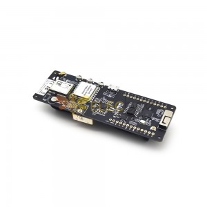
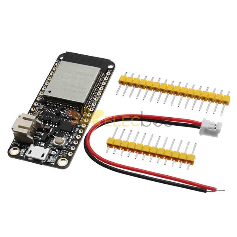
1 x TTGO ESP32 Dev Module WiFi + bluetooth 4MB Flash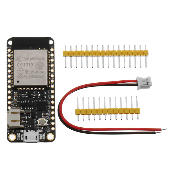

- Reviews (28)
- Q & A
-
: Where is the origin of Elecbee products? Are they certificated?2023-03-03
-
Answer:
Elecbee has long-term cooperation agreements with the OEM factories in China. So that we are able to reduce the intermediate channel cost, and help you save money. Our products are all made strictly according to the relative global standard, to ensure the products have good compatibility and excellent quality.
2023-03-03
-
: What forms of payment do you accept?2023-03-03
-
Answer:
Our main payment methods include Paypal, Credit Cards, Debit Cards, Bank Transfer, and more to discover. Please choose the payment methods in your favor.
2023-03-03
-
: When will you arrange shipment?2023-03-03
-
Answer:
After confirming receipt of your payment. We will arrange the delivery as soon as possible and upload the courier number to the website for you to track.
2023-03-03
-
: How to exchange or return?2023-03-03
-
Answer:
1. You can apply to return within 30 days after receipt of the goods. Please make sure the outside package is intact, and the product is in its original condition. We will arrange your refund according to the relevant provisions once the package is received.
2. Return process: You Apply for a Return - Approve the Return - Arrange a Return - Receive the Products and make Inspection - We arrange a Refund;
3. We will bear the freight charges for returns caused by us, for instance, the quality problem. As to returns caused by the buyer, the buyer should be responsible for the shipping fee.
2023-03-03
Related Products
ZX623W GPS Tracker Module GSM Wifi LBS Locator PCBA SOS Web APP TF Card SMS CoordinateTracking Voice Recorder
Beitian GPS Receiver BS-708 USB GPS Receiver Module Antenna Laptop Replace BU-353S4 BU353S4
SIM868 Development Board GSM GPRS bluetooth GPS Module With Two Antenna