


1. What is an antenna?
An antenna is a device used to send or receive electromagnetic waves.
2. The role of the antenna
The function of the transmitting antenna is to effectively convert the energy of the transmitter's high-frequency current (or guided wave in the waveguide system) into electromagnetic energy in space. The receiving antenna does the exact opposite, so the antenna is actually a transducer.
3. Theoretical basis of antenna
According to Maxwell's electromagnetic field theory, a changing electric field produces a changing magnetic field, and a changing magnetic field produces a changing electric field, thus producing electromagnetic waves.
4. Antenna radiation
To generate radiation there must be a time-varying current or charge with acceleration. In order for the charge to accelerate, the wire must be bent or V-shaped, and its surface may be made discontinuous or terminated.
Charges are added to move at a constant speed in the wire. If the wire is straight and infinitely long, there will be no radiation; if the wire is bent or made into a V shape, it has an end point or is cut off, and its surface is made discontinuous will produce radiation.
If the charges vibrate in a transient state, radiation will be produced even if the wire is straight.
5. Antenna working principle
When the wire carries an alternating current, it can form electromagnetic wave radiation, and the radiation ability is related to the length and shape of the wire;
When the length of the wire increases to be comparable to the wavelength, the current on the wire increases greatly, thus forming stronger radiation. Usually, the above-mentioned straight wires that can generate significant radiation are called oscillators. The wavelength of the conductor is λ/2, where λ is the wavelength of the electrical signal. The signal generator supplies power to the antenna at its center point through a transmission line (also known as the antenna feed). According to this length, voltage and current standing waves will be formed on the entire wire,
The electrical energy input to the antenna is converted into electromagnetic radiation and radiated into the air at the corresponding frequency. The antenna is powered by an antenna feed having a characteristic impedance of 50R and radiating into space with a characteristic impedance of 377R. Antennas of length λ/2are called dipole antennas. But in printed circuit boards, the conductor length mostly used as an antenna is only λ/4, but still has the same performance.
By placing a ground plane some distance below the conductor, a mirror image (λ/4) of the same length as the conductor can be created. When grouped together, these pins act as a dipole antenna. Such antennas are known as quarter-wavelength (λ/4) antennas. Almost all antennas on the PCB are implemented at the quarter-wavelength size on the copper ground plane. Note that the signal is now fed single-ended, with the ground plane used as the return path.
For the quarter-wave antennas used in most PCBs, special attention needs to be paid:
1) Antenna length
2) Antenna feed
3) Shape and size of ground plane and return path
Antenna type
All conductors with a wavelength of λ/4 exposed in free space are placed on a ground plane and provided with a suitable voltage, then the conductor can be used as an antenna. Depending on the wavelength, the antenna may be as long as a car's FM antenna, or as short as the traces on the signal buoy. For 2.4GHz applications, most PCB antennas are of the following types:
1. Wire antenna: This is a piece of wire extended to free space on the PCB, its length is λ/4, and it is placed on the ground plane. This antenna is powered by a transmission line with 50Ω impedance. Typically, the wire antenna provides the best performance and range. The wire can be straight, helical or looped. It is a three-dimensional (3D) structure in which the antenna is 4-5mm above the PCB and protrudes into the space.
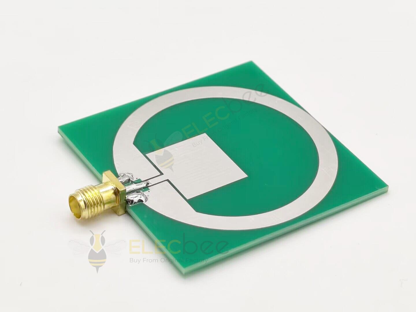
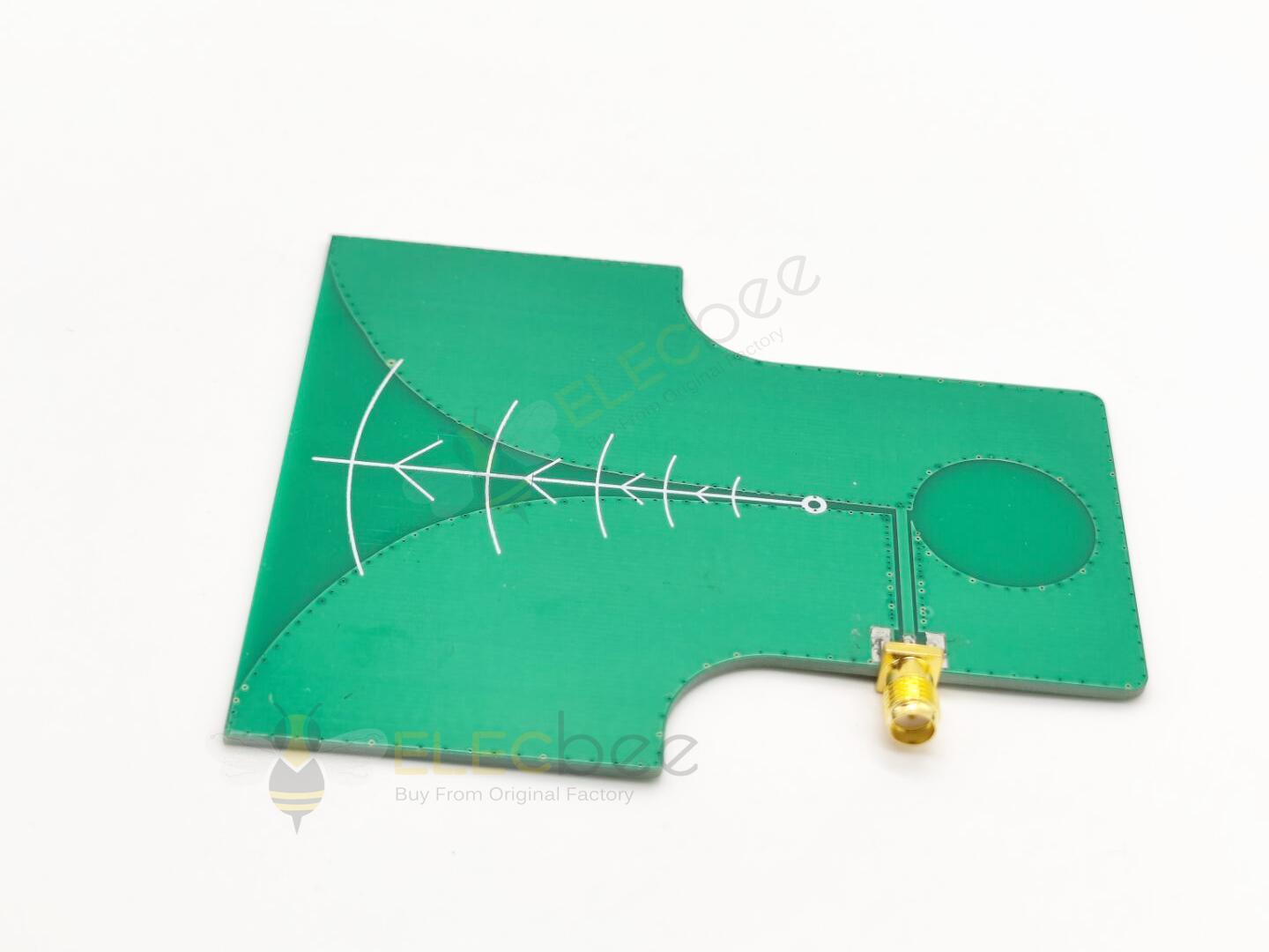
2. PCB antenna: It is a PCB trace on the PCB, and it can be drawn as a straight trace, an inverted F-shaped trace, a serpentine or a circular trace, etc. In a PCB antenna, unlike a wire antenna, the antenna is not exposed to the outside space, but exists as a two-dimensional (2D) structure on the same PCB layer.
Elecbee is a company specializing in the research and development, production and sales of electronic connectors, adapters and antennas. Whether it is technology, research and development, production or business, it is in the leading position in the industry. If you want to know more about our products or need related help and support, you can directly communicate with our technical staff in real time on the website or send an email to service@elecbee.com. All Elecbee staff look forward to cooperating with you.