

로그인
₩KRW
 00
00
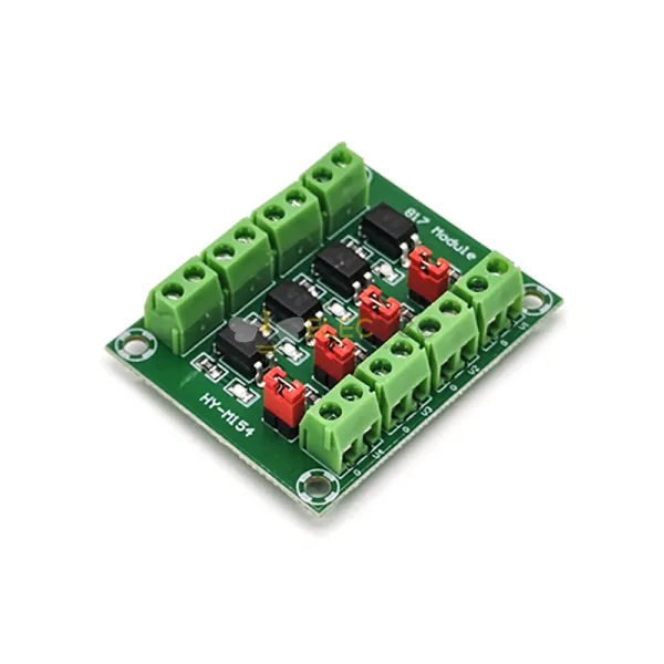
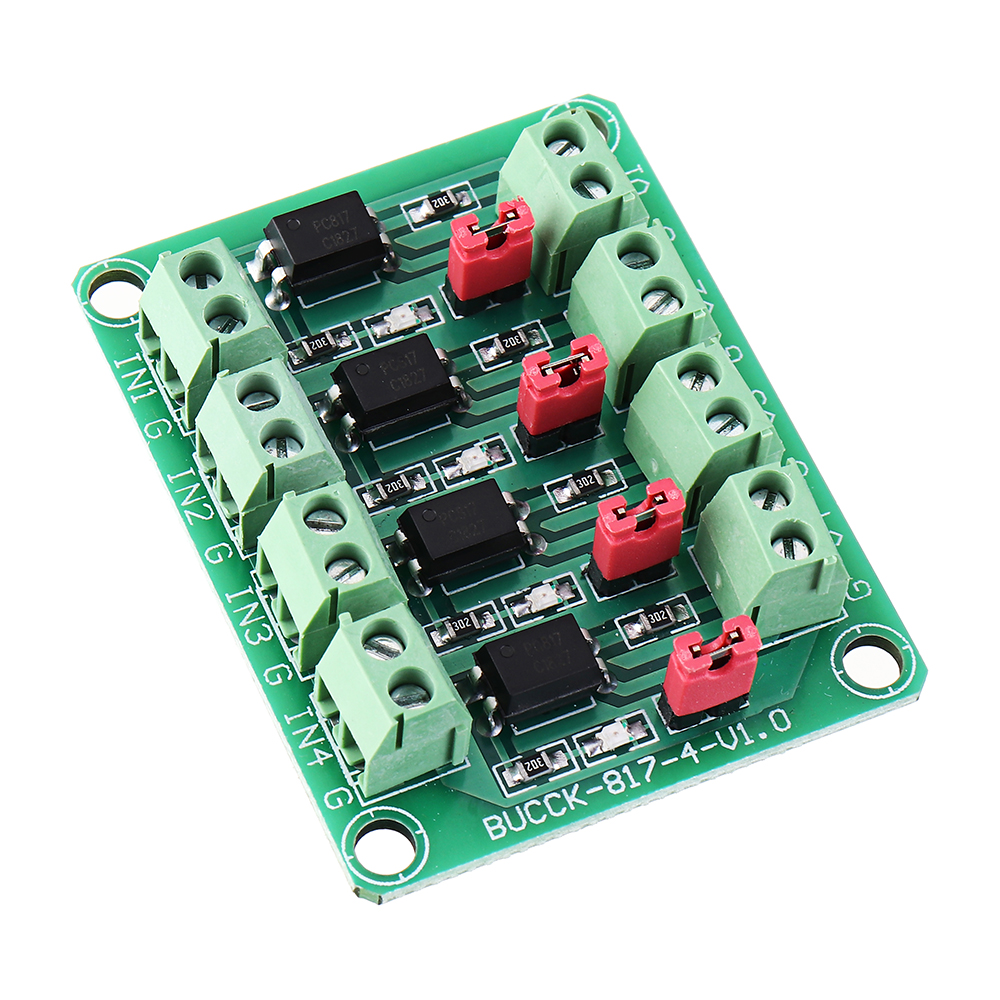
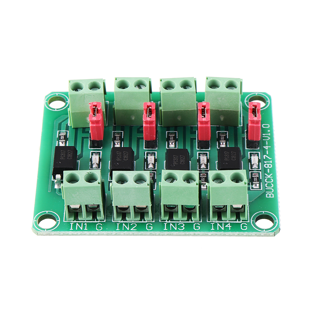
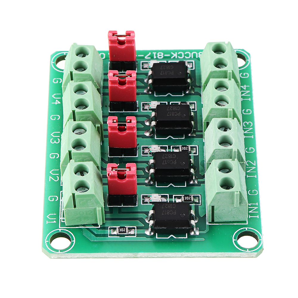
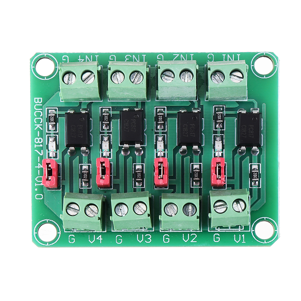
4-CHANNEL PC817 OPTOCOUPLER MODULE: Transfers four independently controlled signals through PC817 optocouplers, helping reduce electrical noise coupling between compatible control and output-side circuits.
3.6–24V CONTROL INPUT: Accepts rated DC control signals from 3.6V to 24V, including compatible 5V controllers and 12V or 24V PLC-style interfaces. Reliable 3.3V operation is not guaranteed because it is below the specified minimum.
3.6–30V, 10mA OUTPUT: Supports output-side voltages from 3.6V to 30V with a conservative maximum output-current limit of 10mA. Use a suitable external driver for relays and other loads requiring higher current.
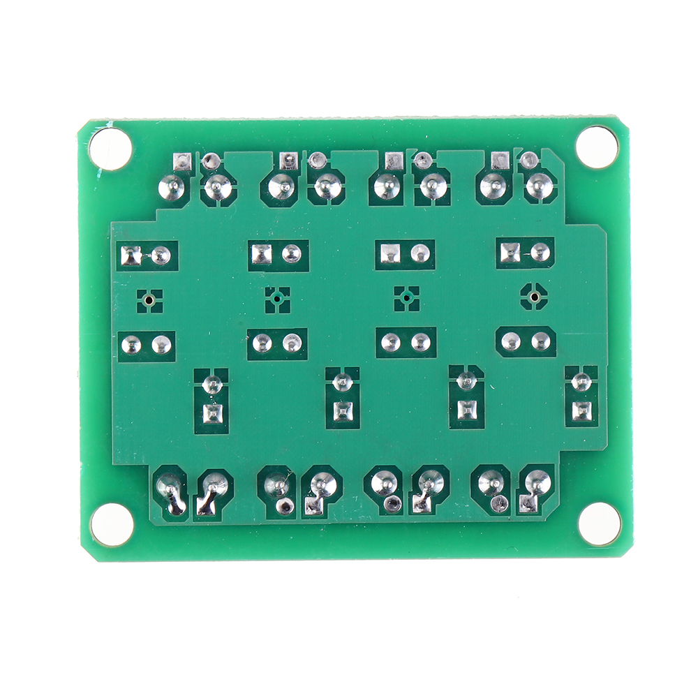
SELECTABLE OUTPUT RESPONSE: Onboard jumper caps provide high-level or pull-down output selection for compatible control interfaces. Configure the required output response according to the labels and wiring diagram on the supplied board.
4kHz RECOMMENDED PULSE LIMIT: Suitable for on/off control and low-frequency pulse signals up to 4kHz. The board measures 48 × 38mm with 42 × 32mm mounting-hole spacing and is not designed for high-speed digital buses.
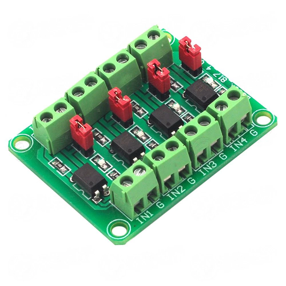
The Elecbee PC817 optocoupler isolation module transfers compatible control signals between circuits operating at different voltage levels. Four optocoupler channels can be controlled independently, making the board suitable for PLC interfaces, industrial switching signals and low-current voltage conversion.
The rated control-input range is 3.6–24V DC, while the output side supports 3.6–30V DC with a conservative maximum output-current limit of 10mA. Onboard jumper caps allow selection between high-level and pull-down output responses.
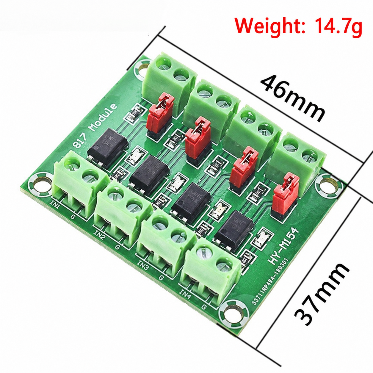
Product Type: Optocoupler isolation and voltage conversion module
Optocoupler: PC817
Number of Channels: 4
Channel Operation: Independently controlled signal channels
Control-Side Input Voltage: 3.6–24V DC
Output-Side Voltage Range: 3.6–30V DC
Specified Output-Current Limit: 10mA maximum
Recommended Maximum Pulse Frequency: 4kHz
Output Selection: High-level or pull-down output via jumper caps
Board Dimensions: 48 × 38mm
Long-Side Hole Spacing: 42mm
Short-Side Hole Spacing: 32mm
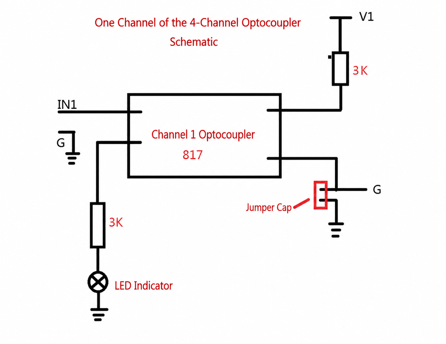
The rated 3.6–24V input range supports compatible 5V controller outputs and higher-voltage 12V or 24V industrial control signals.
3.3V Logic Note: A 3.3V logic-high level is below the specified 3.6V minimum. Some board versions may respond to 3.3V, but reliable operation must be verified with the actual controller, module revision and operating conditions.
The output side supports compatible voltages from 3.6V to 30V DC. Do not exceed the specified 10mA output-current limit, and treat this value conservatively until the loading arrangement for the exact board revision has been confirmed.
The output is intended for signal interfacing and low-current control. Use an appropriate transistor, MOSFET driver, relay driver or other external switching stage when the connected load requires more than 10mA.
Relay Compatibility: Do not connect a relay coil directly unless its required current is confirmed to remain within the module limit. Most higher-current relay coils require an external driver and flyback protection.
The onboard jumper caps select a high-level or pull-down output response. Set the jumpers before applying power and verify the signal polarity required by the receiving circuit.
Although the four optocouplers provide independently controlled signal channels, do not assume that all four channels have separately isolated power rails or grounds. Confirm the PCB markings or wiring diagram when different output-side voltage systems are used.
The module is suitable for on/off switching and compatible low-frequency pulse signals up to the recommended 4kHz limit. Applications include PLC interfaces, industrial control panels, sensor-output isolation, voltage-level conversion and external transistor or MOSFET driver control.
The 4kHz value is a recommended operating limit for this assembled module. It should not be described as the absolute frequency limit of every PC817 optocoupler under all circuit conditions.
The board is not recommended for SPI, I2C, high-speed UART, fast PWM or other interfaces requiring precise high-frequency switching.
Input Range: Keep control signals within the rated 3.6–24V range.
Output Range: Keep the output-side supply within 3.6–30V DC.
Current Limit: Do not exceed the conservative 10mA output limit.
Jumper Configuration: Select the required high-level or pull-down response before power-on.
Preserve Isolation: Avoid connecting the control-side and output-side grounds unless required by the verified circuit design.
External Drivers: Use a suitable driver for relays and other loads requiring higher current.
Pulse Frequency: Keep pulse signals at or below the recommended 4kHz limit.
배송 | 배송 기간 | Elecbee는 일요일을 제외하고 매일 오후 5시경에 주문하신 상품을 발송합니다. 발송 후 예상 배송 시간은 고객님이 선택하신 배송업체에 따라 달라집니다. 특송: 3~7일. 일반 우편: 7~20일. | |
| 배송비 | 주문 배송비는 장바구니에서 확인할 수 있습니다. | ||
| 배송 옵션 | 저희는 특송 및 일반 배송 서비스를 제공합니다. | ||
| 물류 추적 | 주문 발송 후 이메일로 운송장 번호를 보내드리며, 「내 주문 추적」 기능으로 물류를 조회할 수 있습니다. | ||
| 반품/보증 | 반품 | 반품/교환은 일반적으로 발송 후 30일 내에 완료해야 하며, 고객 서비스에 연락하여 반품 승인을 받으세요. 상품은 사용하지 않은 상태여야 하며 원래 포장을 유지해야 합니다. 배송비는 고객이 부담합니다. | |
| 보증 | 모든 Elecbee 구매 상품은 30일 무조건 반품 정책과 1년 Elecbee 보증(제조 결함 대상)을 받습니다. | ||
| 본 보증은 고객의 잘못된 조립, 설명서 미준수, 제품 수정, 부주의 또는 부적절한 사용으로 인한 결함 상품에는 적용되지 않습니다. | |||
| 주문 | 구매 방법 | Elecbee는 온라인 주문을 지원합니다. | |
| 장바구니에 추가 > 결제 > 주문 제출 > 결제 완료 > 배송 | |||
| 결제 | PayPal, 신용카드(Visa, MasterCard, 아메리칸 익스프레스), 은행 송금. | ||
