

Vehicle Electrical Systems: Decentralized, Domain and Zone Architectures
Traditional decentralized vehicle architectures consist of up to 100 control units, each assigned a defined function, such as controlling the engine control unit (ECU), airbags, ABS/ESP, seat adjustment system or climate control. Each controller works autonomously and communicates with the other control units through a gateway. As vehicle features are added or improved, a control unit is added for each new feature. All vehicle types have changed dramatically in recent years, from van fleet vehicles to buses to automobiles, and the increase in the number of features has greatly increased the wiring and interconnect content of each vehicle.
The control units in a domain architecture are organized into functional areas, each responsible for a specific area of the vehicle, such as the powertrain, infotainment system or safety functions. A separate high-performance computer (HPC) performs the primary control of the domain and coordinates the control units within its domain. For example, the safety domain oversees the control units for driver assistance systems, ABS/ESP and steering systems. The domain architecture reduces the number of control units and reduces the amount of wiring and installation work required compared to traditional decentralized architectures, thus effectively reducing weight and costs. Additional functions can be easily integrated into upgrades or new designs.
In a regional architecture, the build is not based on the domain, but on the local region. For example, multiple functions are bundled into one area within the vehicle. Functions such as the drivetrain and infotainment system can be combined and processed in a single zone controller. A central HPC performs the primary control of the various zone controllers, reducing the number of control units and the consequent amount of wiring by 50 percent.
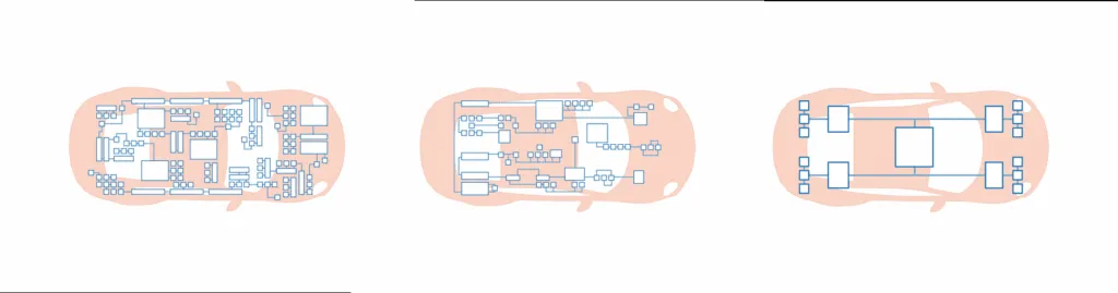
Figure 1: Schematic representation of the electrical system architecture of a high-performance vehicle. Illustration: ept GmbH
High Reliability and Performance Requirements
HPCs and their corresponding interconnect modules must be designed for the highest performance requirements. For example, the processing of imaging and sensor data in automated driving safety systems requires safe, high-speed data transfer rates and short latency times. At the same time, signaling must not fail under any circumstances. High performance, fast and, above all, reliable data transfer rates - sometimes under harsh environmental conditions - are the requirements for connectors in these systems.
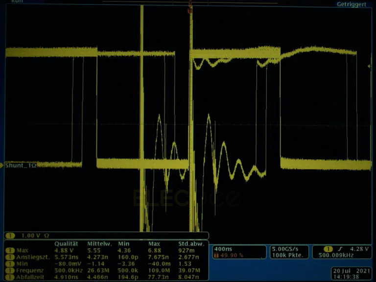
The “readability” of a signal can be illustrated by an eye diagram, which shows whether the signals emitted in the receiver can be uniquely assigned to the digital state 1 or 0. For this purpose, the signals are recorded, superimposed and displayed with an oscilloscope via defined transmission paths. In this way, the signal routes can be mapped and overlapped. According to the theory, the transitions of the logical states are infinitely steep and the signal lines are completely superimposed. External disturbing factors and internal damage to the signal pair flatten the signal rise while the amplitude level changes.
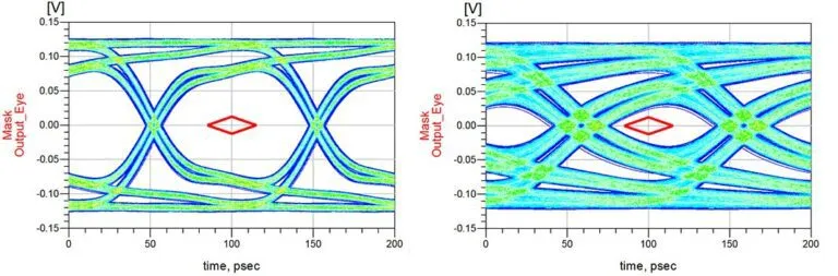
Fig. 2: Eye diagrams are used to assess signal quality at digital data transmission rates. Illustration: ept GmbH (Colibri)
The so-called “eye patch” can be seen in the center of the diagram. It is not possible to clearly assign signals in this area.
Both eye diagrams illustrate the effect of cable length and impedance using 16+ Gb/s and 10 Gb/s ept Colibri plug connectors. This example illustrates how significant improvements in signal integrity can be realized by further developing the contact design. By using a shorter cable length and an impedance of 100 Ω, the eye diagram of the 16+ Gb/s Colibri variant can be formed much more clearly than the previous 10 Gb/s Colibri variant - the signal pairs can be clearly interpreted.
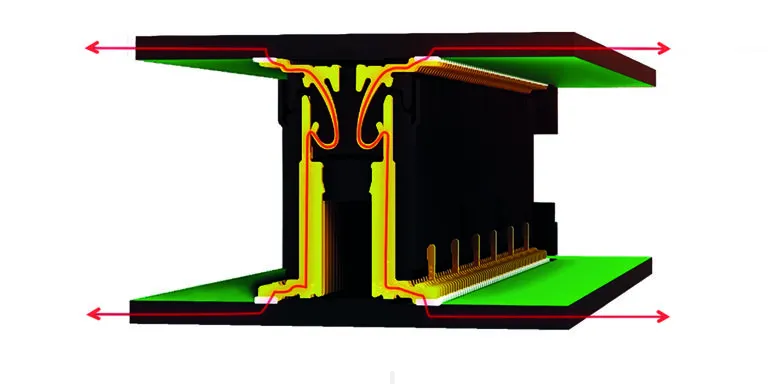
Figure 3: Colibri's optimized contact design enables low-loss, high-speed data rates. Illustration: ept GmbH (Colibri)
High-speed signals require special signal protection because they are particularly susceptible to electromagnetic influences. In this case, the connector can act as both a source and a receiver of interference. Shielding plates will protect sensitive signals from external influences.
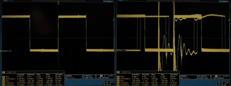
Figures 4 and 5: Signal interference when using shielded (top) and unshielded (bottom) connectors
The connector can be described by considering the electrical conditions as a function of both source and sink, and the coupling inductance LK is used as an EMC parameter. Henry (H) is used to express this value. This applies to immunity and interference emission. If the induced voltage (Uind), generator voltage (UGen), and generator constant (kGen) are known, the following formula can be used to determine the specific maximum allowable coupling inductance (L) for the application:
Coupling inductance also helps the user to define the appropriate connector for their EMC requirements and helps to avoid costly and time sensitive trial and error testing. An example is as follows: At 4.4 kV, determine the case-specific maximum coupling inductance for HDMI signals to be 47 picohyen (pH). If this value is higher, the signal can no longer be transmitted without interference.
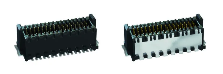
Figure 6: Unshielded (left) and shielded (right) versions of the connector.
Electromagnetic influences can jeopardize the transmission of high-speed signals. Connectors, especially in high-performance vehicle applications, are exposed to extreme environmental conditions such as vibration and shock. Connectors must be particularly robust to ensure uninterrupted signal transmission even in harsh environments. The main decisive factors in this context are contact design, contact systems and termination technology.
Strategic contact design for reliability in harsh environments
Conventional two-piece connectors have one male and one female contact. However, in the event of strong shocks, the male connector may disengage from the female connector. To prevent this contact breakage, a double-sided female connector can be used to provide redundancy and thus increase contact reliability, as the second female contact ensures that the signal is always transmitted through at least one contact (Figure 5).
No (left) and (right) double-sided female contacts exposed to shock.
Connectors with “gender-neutral” terminal systems are more robust. The special feature here is that the connector pair - plug and socket - has the same contact geometry. Therefore, both have both female and male contacts. As a result, each pin is contacted by two female contacts and the plug and socket are interlocked and cannot be lifted from each other. The double-sided female connector always ensures at least one contact when subjected to mechanical loads, while the interlocking geometry in the neutral contact system ensures that the signal is always transmitted through both contacts. This high degree of redundancy therefore achieves maximum contact reliability (Fig. 5).
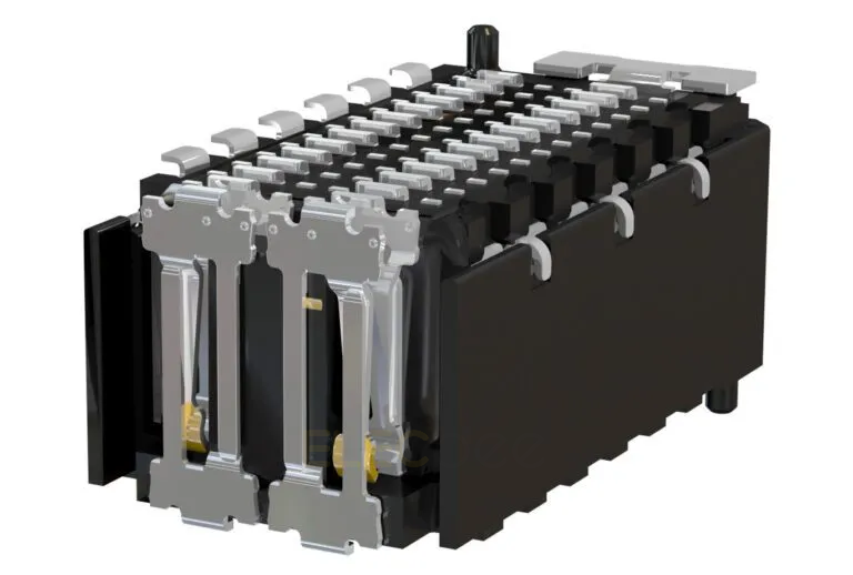
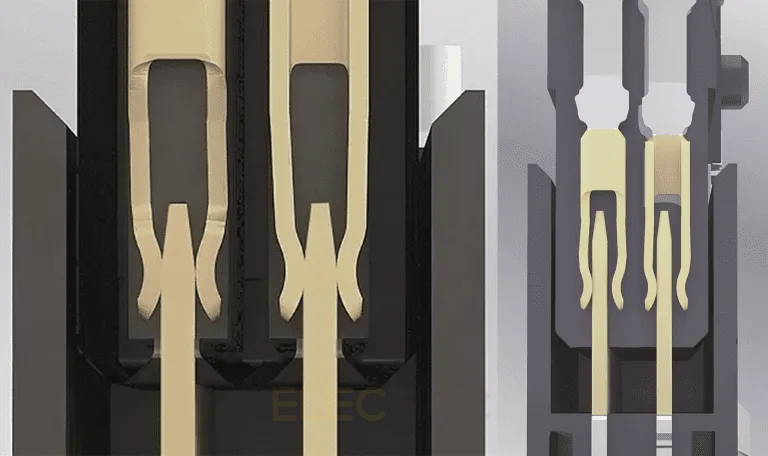
Figure 7: Cross-section of a Zero8 connector showing the gender-neutral terminal system.
In order to achieve a durable connection between PCB and connector, we recommend the use of Surface Mount Technology (SMT) as a termination technique. Solder paste is used to solder the connector to the designated connection surface of the PCB: the solder pads. The solder is first melted and then hardened in a so-called reflow oven. SMT allows a stable connection to be established between connector and PCB. However, a number of criteria must be met in order to achieve this. First of all, the correct ratio of pins, pads and paste must be maintained in order to create solder joints that comply with IPC A-610. This is the only way to achieve a high-quality connection according to IPC Class 3, which means it is suitable for high-performance automotive electronics. This class stipulates that signal transmission failures must not occur. The optimum solder connection can be recognized by the uniform formation of the curved moon face. The entire circumference of the contact must be closed with a moon-curve solder in order to achieve the best possible retention force on the PCB. (Figure 7).
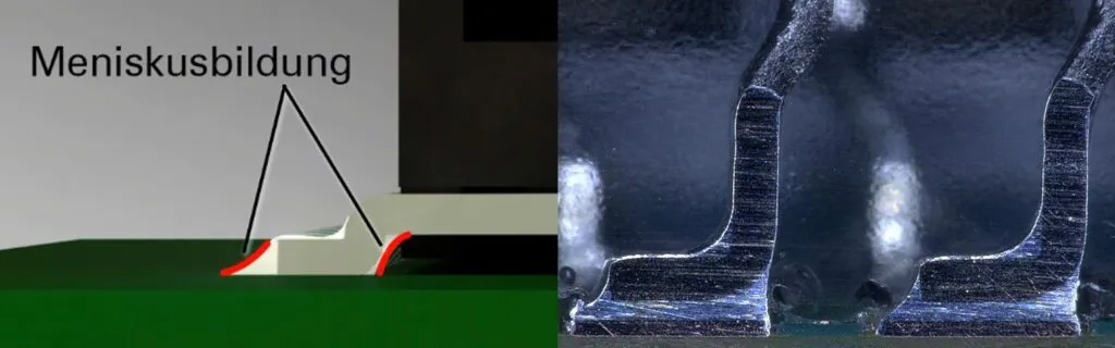
Figure 8: Uniform formation of the curved moon face around the soldering foot
The contact feet must be coplanar for an excellent connection. This coplanarity is checked by a fully automated process.
At first glance, the role of connectors in high-performance vehicle systems may seem to be fading into obscurity due to the reduction in the number of control units. However, a closer look reveals that it is precisely because of this shift to centralized data processing via HPC that their role is becoming increasingly important. The reliability of signal transmission has never been more important.