

 0
0
Кабельный ввод M20 не обязательно подходит для кабеля диаметром 20 мм. Это одна из самых распространенных—и дорогостоящих—ошибок при выборе кабельного ввода. Маркировка M20 обычно обозначает присоединительную резьбу, а диаметр кабеля, который можно надежно герметизировать, определяется отдельным диапазоном зажима.
В этом руководстве объясняется, как выбрать кабельный ввод с учетом наружного диаметра кабеля, диапазона зажима, присоединительной резьбы, длины резьбы, материала и требований к степени защиты. Также рассматриваются сложные ситуации, которые регулярно возникают при реальном монтаже: очень тонкие кабели, имеющиеся отверстия в корпусах, предварительно оконцованные кабели RJ45, несколько кабелей в одном вводе и наружные коробки, в которых продолжает скапливаться вода.
Краткий ответ
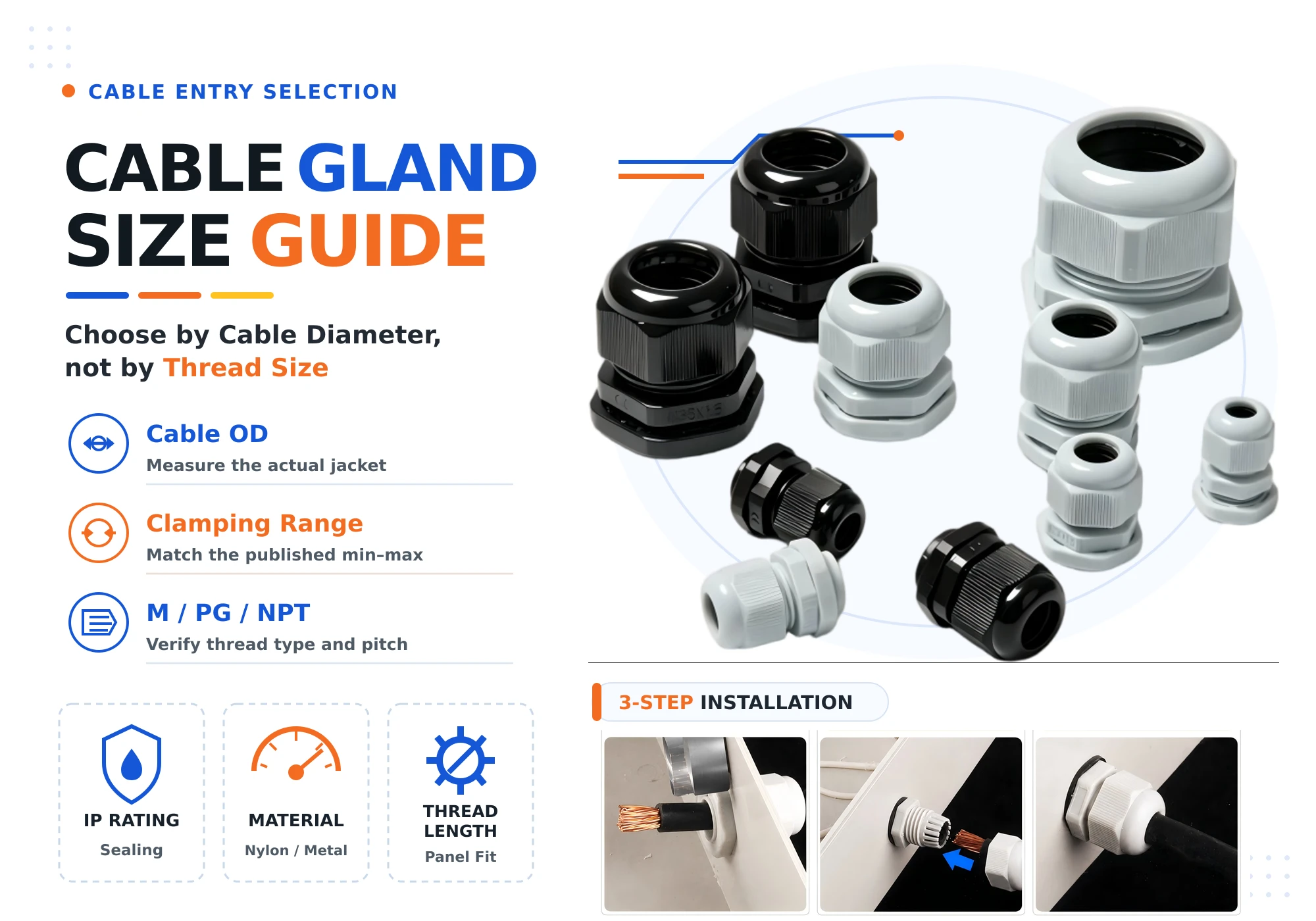
Сначала выберите кабельный ввод по измеренному наружному диаметру кабеля. Затем проверьте резьбу или монтажное отверстие корпуса, доступную длину резьбы, способ герметизации, материал, температурный диапазон и степень защиты IP завершенной конструкции. Никогда не выбирайте кабельный ввод только по обозначению M, PG или NPT.
1. Почему размеры кабельных вводов легко понять неправильно
Размер резьбы и размер кабеля — это разные характеристики
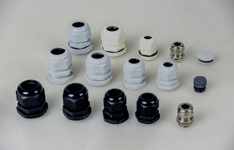
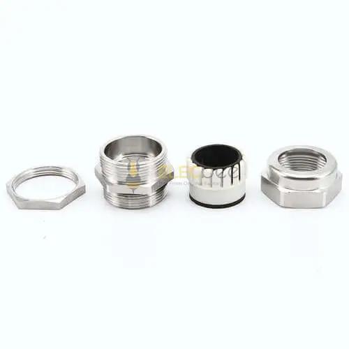
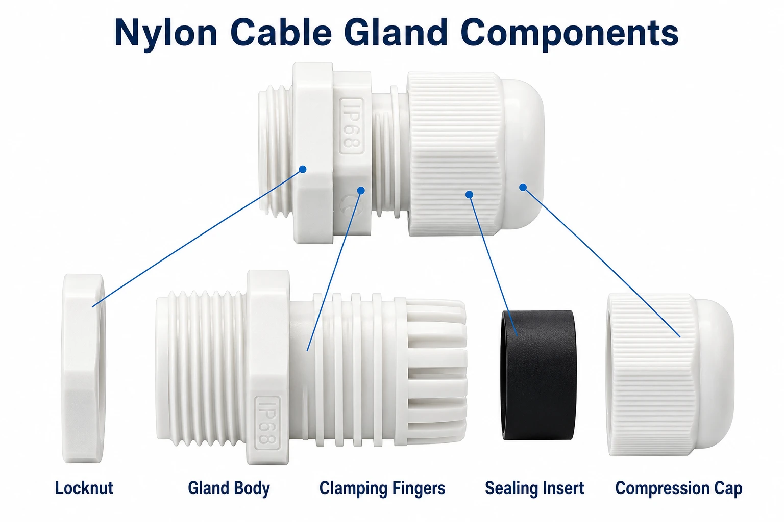
Кабельный ввод имеет два сопряжения: одно с корпусом, другое с кабелем. Присоединительная резьба соединяет ввод с панелью, распределительной коробкой или корпусом оборудования. Уплотнительная вставка обжимает оболочку кабеля. Эти сопряжения связаны конструкцией изделия, но не имеют одинаковых размеров.
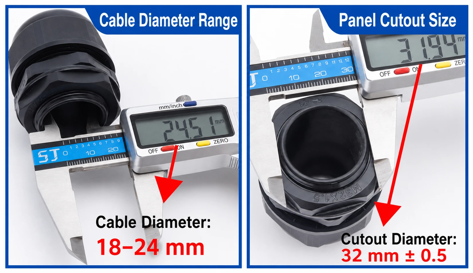
Например, M20 × 1.5 обозначает метрическую присоединительную резьбу с номинальным наружным диаметром 20 мм и шагом 1,5 мм. Это не гарантирует, что кабель диаметром 20 мм пройдет через ввод или будет герметизирован надлежащим образом. В зависимости от серии ввода и уплотнительной вставки изделие M20 может иметь диапазон зажима 6–12 мм, 6–13 мм или другой диапазон, установленный производителем.
| Характеристика | Что она определяет | Пример | Распространенная ошибка |
|---|---|---|---|
| Присоединительная резьба | Совместимость с корпусом | M20 × 1.5 | Предположение, что M20 подходит для кабеля диаметром 20 мм |
| Диапазон зажима | Наружные диаметры кабелей, которые можно герметизировать и зафиксировать | 6–13 мм | Проверка только максимального диаметра |
| Длина резьбы | Допустимая толщина стенки и глубина зацепления резьбы | 8 мм | Покупка ввода с короткой резьбой для толстостенного корпуса |
| Свободное проходное отверстие | Возможность физически провести кабель или разъем | Зависит от изделия | Игнорирование крупного предварительно установленного разъема |
| Степень защиты IP | Испытанная защита от твердых частиц и воды при указанных условиях | IP68 | Предположение, что любая установленная конструкция сохраняет степень IP68 |
Почему ввод с более крупной резьбой может иметь меньшее уплотнительное отверстие
В одной установке могут одновременно использоваться большое отверстие в корпусе и кабель малого диаметра. Поэтому производители предлагают уменьшающие зажимные вставки, съемные внутренние вставки и различные диапазоны уплотнения для одного размера резьбы. Это позволяет герметизировать тонкий кабель в имеющемся отверстии M20 без установки отдельного резьбового переходника.
Такая конструкция удобна, однако переход с M16 на M20 не гарантирует увеличения диапазона диаметров кабеля. Всегда проверяйте минимальный и максимальный диаметры кабеля, а не оценивайте резиновую вставку только по маркировке резьбы.
Четыре размера, которые необходимо записать перед заказом
- Наружный диаметр кабеля: Измерьте готовую оболочку в месте уплотнения.
- Размер и резьба ввода: Определите, используется ли метрическая резьба, PG, NPT или обычное сквозное отверстие.
- Толщина стенки корпуса: Убедитесь, что длины резьбы достаточно для контргайки или полного резьбового зацепления.
- Максимальный проходной размер: Измерьте любой разъем RJ45, клемму, наконечник или литой разъем, который невозможно снять.
2. Как выбрать правильный размер кабельного ввода
Шаг 1. Измерьте фактический наружный диаметр кабеля
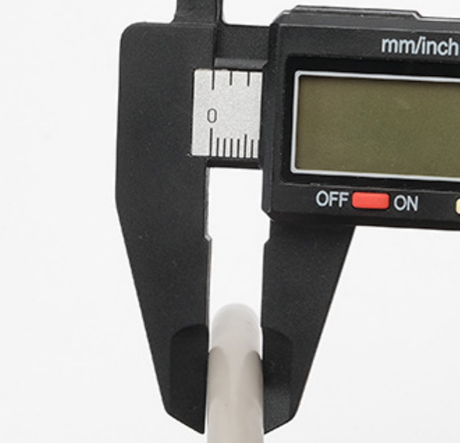
Используйте штангенциркуль, чтобы измерить кабель в месте, где его будет обжимать уплотнительная вставка. Не выбирайте ввод по сечению проводника, размеру AWG, количеству жил или номинальному названию семейства кабелей. Наружные диаметры 5-жильного силового и 5-жильного управляющего кабелей могут существенно различаться.
Измеряйте обычную оболочку—не этикетку, участок ремонта с термоусадкой, гофрированную трубку или деформированную часть. Для овального или кабеля неправильной формы измерьте большую и малую оси и выберите ввод или вставку, предназначенные для соответствующего профиля кабеля.
Шаг 2. Сопоставьте кабель с указанным диапазоном зажима
Диаметр кабеля должен находиться между минимальным и максимальным значениями диапазона зажима, указанного производителем. Кабель меньше минимального размера может фиксироваться и герметизироваться недостаточно надежно. Кабель больше максимального размера может повредить вставку, помешать сборке или создать чрезмерную нагрузку на оболочку.
По возможности не выбирайте кабель, диаметр которого точно совпадает с предельным значением диапазона, особенно если ожидаются допуски оболочки, перепады температуры или регулярное перемещение. Размер ближе к середине диапазона обычно обеспечивает больший монтажный запас, однако определяющими остаются данные производителя.
Шаг 3. Сопоставьте резьбу, шаг и отверстие корпуса
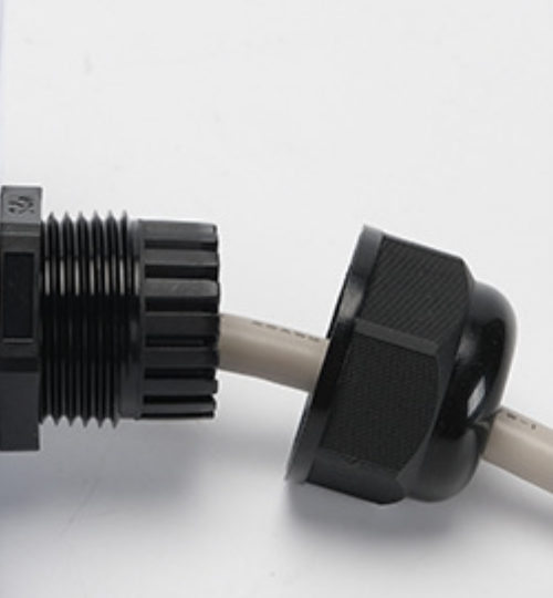
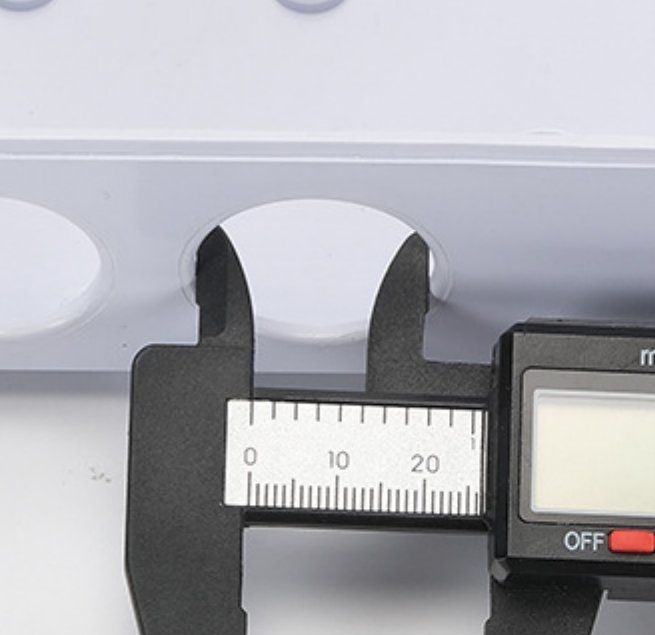
Убедившись в совместимости ввода с кабелем, определите тип интерфейса корпуса. Для резьбового ввода необходимо сопоставить как обозначение резьбы, так и ее шаг. Для обычного сквозного отверстия проверьте рекомендуемый диаметр выреза и используйте соответствующую контргайку, уплотнительную шайбу или уплотнительное кольцо.
Не пытайтесь силой установить метрический ввод в отверстие PG и не считайте визуально похожий размер NPT взаимозаменяемым. Частичное зацепление может казаться плотным, но обеспечивать слабую фиксацию, повреждать резьбу и создавать ненадежное уплотнение от воздействия окружающей среды.
Шаг 4. Проверьте длину резьбы, материал и условия эксплуатации
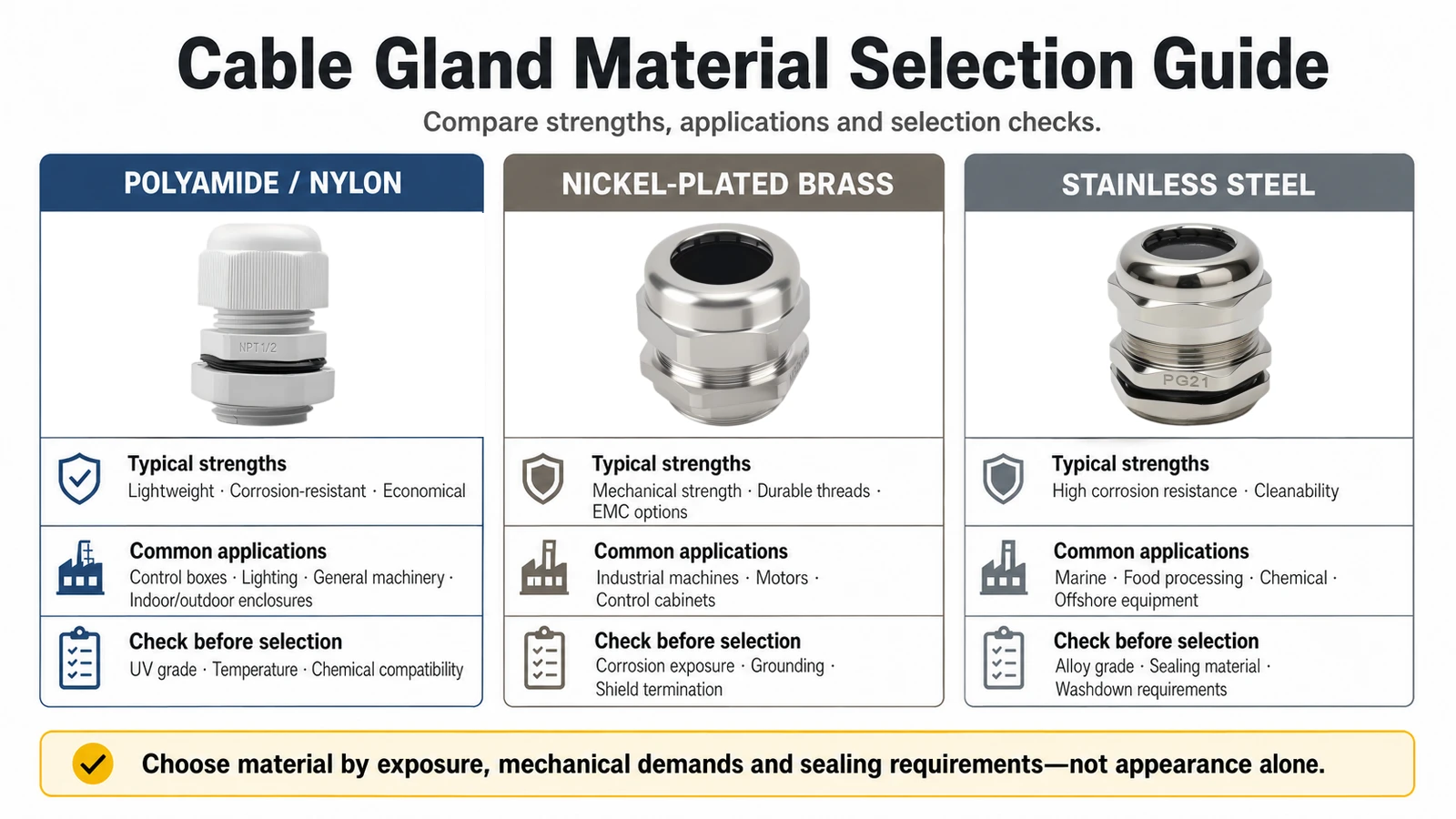
Для толстостенного литого корпуса может потребоваться ввод с удлиненной резьбой, а для тонкой металлической панели может подойти стандартная резьба с контргайкой. Затем оцените условия эксплуатации: воздействие ультрафиолета, масел, химических веществ, мойки под давлением, солевого тумана, температуры, ударов и требования электромагнитной совместимости могут влиять на выбор материала и конструкции.
- Измерьте наружный диаметр кабеля.
- Определите, является ли кабель круглым, плоским, многокабельным или предварительно оконцованным.
- Выберите диапазон зажима, включающий измеренный диаметр.
- Точно сопоставьте систему и шаг резьбы с корпусом.
- Проверьте размер монтажного отверстия, толщину стенки и длину резьбы.
- Выберите конструкцию из нейлона, латуни, нержавеющей стали, исполнение EMC или специализированный вариант.
- Подтвердите требуемую степень защиты IP, наличие сертификации и соблюдение инструкции по монтажу.
| Материал | Типичные преимущества | Распространенные области применения | Что проверить перед выбором |
|---|---|---|---|
| Полиамид/нейлон | Малый вес, устойчивость к коррозии и доступная стоимость | Коробки управления, освещение, общепромышленное оборудование, внутренние и наружные корпуса | Стойкость к УФ-излучению, температура и химическая совместимость |
| Никелированная латунь | Механическая прочность, долговечная резьба и варианты EMC | Промышленное оборудование, двигатели и шкафы управления | Воздействие коррозии, заземление и подключение экрана |
| Нержавеющая сталь | Высокая коррозионная стойкость и удобство очистки | Морское оборудование, пищевая и химическая промышленность, морские платформы | Марка сплава, материал уплотнения и требования к мойке |
3. Сравнение метрических, PG- и NPT-кабельных вводов
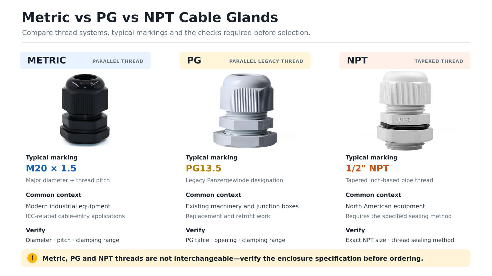
Метрическая резьба кабельных вводов
Для метрических кабельных вводов обычно используются такие обозначения, как M12 × 1.5, M16 × 1.5, M20 × 1.5 и M25 × 1.5. Первое число обозначает номинальный наружный диаметр резьбы, а второе — ее шаг. Метрическая присоединительная резьба широко используется в современном промышленном оборудовании и в применении кабельных вводов регулируется требованиями, связанными со стандартами IEC.
Резьба PG кабельных вводов
PG, или Panzergewinde, представляет собой устаревшую систему резьбы, которая по-прежнему встречается в существующем оборудовании, распределительных коробках и продукции, предназначенной для разных рынков. Обозначение PG нельзя считать прямым указанием метрического диаметра кабеля или отверстия. Используйте таблицу резьбы PG и данные диапазона зажима, предоставленные производителем. Европейское оборудование в основном перешло на метрические вводы, однако изделия PG остаются актуальными для замены и модернизации.
Резьба NPT кабельных вводов
NPT — это коническая трубная резьба с размерами в дюймах, широко применяемая в североамериканском оборудовании. По размерам и функциям она отличается от параллельной метрической резьбы и PG. Точно сопоставляйте обозначение NPT и соблюдайте указанный способ герметизации; не заменяйте ввод NPT визуально похожим метрическим вводом или PG.
| Система резьбы | Типичная маркировка | Общая форма | Основной критерий выбора |
|---|---|---|---|
| Метрическая | M20 × 1.5 | Параллельная метрическая резьба | Сопоставить наружный диаметр, шаг и диапазон зажима |
| PG | PG9, PG13.5, PG21 | Параллельная устаревшая резьба | Использовать фактическую таблицу размеров PG, не переводить обозначение напрямую в миллиметры |
| NPT | 1/2" NPT | Коническая дюймовая трубная резьба | Сопоставить размер NPT и указанный способ герметизации резьбы |
Важно: Таблица соответствия может помочь определить возможные варианты, но она не делает метрическую резьбу, PG и NPT взаимозаменяемыми. Перед заказом переходника или сменного кабельного ввода проверьте фактические характеристики корпуса.
4. Кабельные вводы для тонких, нескольких и предварительно оконцованных кабелей
Как герметизировать тонкий кабель диаметром около 3 мм
Если кабель диаметром 3 мм меньше минимального зажимного диаметра ввода, более сильная затяжка не станет надежным решением. Выберите меньший диапазон зажима, одобренную производителем уменьшающую вставку или ввод, специально предназначенный для кабелей малого диаметра. Для сертифицированного или критически важного с точки зрения безопасности оборудования нельзя считать, что самодельные втулки из шланга, клейкая лента или залитый силикон сохранят исходную степень защиты IP, разгрузку от натяжения или сертификацию.
Как провести кабель с разъемом RJ45 или литым разъемом
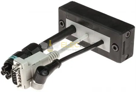
Обычный кабельный ввод увеличенного размера может пропустить разъем, но затем оставить слишком большой зазор вокруг оболочки кабеля. Оптимальным решением обычно является разъемный кабельный ввод для предварительно оконцованного кабеля, разъемная рама кабельного ввода или специально разработанный проходной интерфейс. Разъемная вставка замыкается вокруг кабеля после прохождения разъема, что позволяет избежать повторного оконцевания на месте монтажа.
Это также соответствует современному направлению развития кабельных вводов: модульные разъемные системы подходят для заводских кабельных сборок Ethernet, сервоприводов, линий передачи данных и питания, одновременно упрощая модернизацию и обслуживание. Возможности изделий различаются, поэтому проверяйте диаметр кабеля, размеры разъема, разгрузку от натяжения и номинальную степень защиты IP конкретной конфигурации.
Как провести несколько или плоских кабелей через один ввод
Не зажимайте два или более круглых кабеля в стандартной одноотверстной вставке. Углубления между кабелями образуют пути утечки и приводят к неравномерному зажиму. Используйте многоотверстную уплотнительную вставку, рассчитанную на каждый кабель, многокабельный ввод или модульную систему кабельного ввода. Для плоского кабеля также необходима плоская вставка, соответствующая его профилю, а не круглое уплотнение.
| Проблема при монтаже | Рекомендуемое решение | Чего следует избегать |
|---|---|---|
| Кабель меньше минимального диапазона зажима | Ввод меньшего размера или одобренная уменьшающая вставка | Чрезмерная затяжка или использование клейкой ленты |
| Разъем RJ45 или литой разъем крупнее кабеля | Разъемный ввод, разъемная вводная рама или проходной разъем | Увеличенный одноотверстный ввод с открытым зазором |
| Несколько кабелей должны проходить через одно отверстие панели | Многоотверстная вставка или модульный многокабельный ввод | Проведение пучка кабелей через одно круглое уплотнение |
| Плоский или ленточный кабель | Плоская вставка, соответствующая профилю кабеля | Принудительная установка в стандартное круглое уплотнение |
5. Как правильно установить водонепроницаемый кабельный ввод
Понимайте, что включает степень защиты IP
Стандарт IEC 60529 классифицирует защиту корпусов от твердых частиц и воды. Кабельный ввод может продаваться с определенной степенью IP, однако защита готового корпуса зависит от всей установленной конструкции: правильного диаметра кабеля, неповрежденного уплотнения, совместимой поверхности корпуса, правильного монтажного отверстия, уплотнительной шайбы или кольца, достаточного резьбового зацепления и правильной затяжки.
IP68 не следует трактовать как единую универсальную глубину погружения или возможность неограниченной эксплуатации под водой. Допустимые глубина и продолжительность, превышающие условия IPX7, определяются для конкретного испытанного изделия. Проверьте указанные производителем условия испытаний и убедитесь, что степень защиты распространяется на используемую собранную конфигурацию.
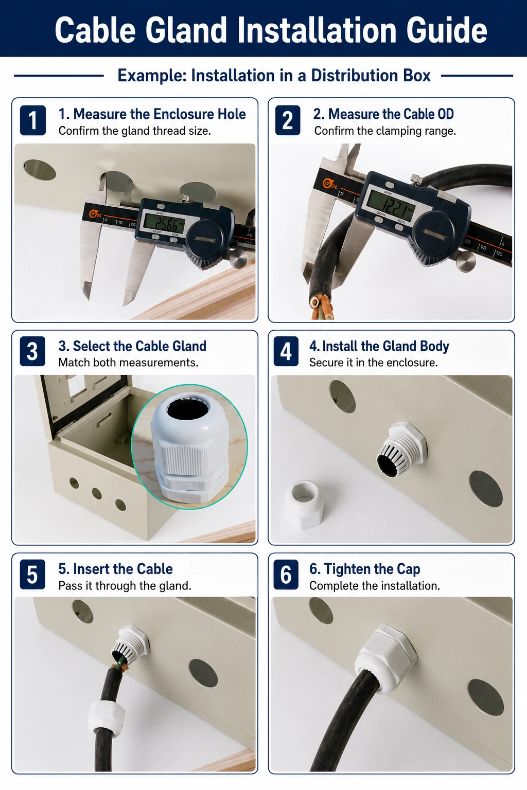
Порядок монтажа в наружном корпусе
- До сверления убедитесь, что кабельный ввод, кабель и корпус совместимы.
- Выполните монтажное отверстие указанного размера и удалите заусенцы, не увеличивая диаметр сверх нормы.
- Ровно установите уплотнение корпуса ввода или уплотнительное кольцо на чистую и подходящую поверхность корпуса.
- Закрепите ввод в сквозном отверстии подходящей контргайкой; полностью установите резьбовой ввод, не допуская перекоса резьбы.
- Проведите кабель и разместите неповрежденный круглый участок оболочки в зоне уплотнения.
- Затяните корпус и колпачок ввода в соответствии с инструкциями производителя или указанным моментом затяжки.
- Проверьте фиксацию контролируемым натяжением, осмотрите уплотнение и выполните требуемое испытание корпуса.
Для наружных коробок по возможности выбирайте боковой или нижний кабельный ввод и формируйте перед входом капельную петлю. Эти меры снижают прямое воздействие воды, но не заменяют правильно подобранные и установленные кабельный ввод и корпус с соответствующей степенью защиты.
Распространенные ошибки монтажа и виды отказов
| Ошибка | Вероятный результат | Исправление |
|---|---|---|
| Выбор только по маркировке M, PG или NPT | Кабель не подходит или не герметизируется | Проверяйте резьбу и диапазон зажима отдельно |
| Диаметр кабеля меньше минимального | Слабая фиксация и путь для проникновения воды | Используйте меньший диапазон или одобренный переходник |
| Несколько кабелей в одном одноотверстном уплотнении | Зазоры между оболочками кабелей | Используйте многоотверстную вставку |
| Неправильная или частично зацепленная резьба | Повреждение ввода и ненадежное уплотнение | Точно сопоставьте стандарт и шаг резьбы |
| Резьба слишком короткая для стенки | Недостаточное зацепление контргайки или резьбы | Выберите вариант с удлиненной резьбой |
| Верхний ввод без отвода воды | Повышенное воздействие стоячей или направленной воды | По возможности используйте боковой/нижний ввод и капельную петлю |
| Использование ленты или силикона в качестве основного уплотнения | Сложное обслуживание и непроверенные характеристики | Используйте сертифицированное решение, предназначенное для конкретного кабеля |
6. Два практических примера выбора кабельного ввода
Пример 1. Ввод M16 слишком мал, но вставка M20 также кажется слишком маленькой
У монтажника есть кабель, который не входит в кабельный ввод M16, поэтому он заказывает ввод M20. Ввод M20 поставляется с уменьшающей вставкой и короткой присоединительной резьбой. Кабель по-прежнему не подходит, а ввод невозможно закрепить в толстой стенке корпуса.
Ошибка заключается в том, что M20 воспринимается как допустимый диаметр кабеля. Правильный порядок действий — измерить наружный диаметр кабеля, выбрать изделие, опубликованный диапазон зажима которого включает это значение, а затем подобрать правильную длину резьбы. Если в корпусе уже имеется отверстие M20, может подойти ввод M20 с соответствующей полноразмерной вставкой; для толстой стенки также может потребоваться вариант с удлиненной резьбой.
Пример 2. Предварительно оконцованный кабель камеры PoE необходимо ввести в наружную коробку
Разъем RJ45 значительно шире кабеля Ethernet. Обычный ввод, достаточно большой для прохождения разъема, может оказаться неспособным затем герметизировать оболочку кабеля. Снятие и повторная установка разъема требуют дополнительных инструментов и трудозатрат, а также могут повлиять на надежность соединения.
Разъемный кабельный ввод или разъемная вводная рама позволяют провести оконцованный кабель, после чего правильно подобранная разъемная вставка замыкается вокруг оболочки. Установите распределительную коробку так, чтобы ввод был защищен, направьте открытый кабель вниз, сформировав капельную петлю, и разместите соединение внутри корпуса. Одна лишь изоляционная лента не должна служить основным средством защиты от окружающей среды.
7. Часто задаваемые вопросы о размерах кабельных вводов
7.1 Вопросы о размерах и резьбе
Означает ли M20, что кабельный ввод подходит для кабеля диаметром 20 мм?
Нет. M20 обозначает номинальный диаметр метрической присоединительной резьбы. Совместимость с кабелем определяется диапазоном зажима и свободным проходным отверстием изделия.
Какой кабельный ввод следует использовать для кабеля диаметром 3 мм?
Выберите ввод или одобренную производителем уменьшающую вставку, опубликованный диапазон зажима которых включает 3 мм. Не считайте PG7 подходящим, не проверив фактический минимальный и максимальный диаметры кабеля.
Что означает PG9?
PG9 — это стандартизированное обозначение устаревшей резьбы, а не гарантия того, что любой ввод PG9 герметизирует кабель диаметром 9 мм. Проверьте размеры резьбы PG, требуемое отверстие корпуса и диапазон зажима конкретного ввода.
Можно ли заменить кабельный ввод M16 на M20?
Только если корпус рассчитан на ввод M20 или подходящий переходник, а выбранный ввод M20 имеет правильный диапазон зажима. Более крупная резьба сама по себе не подтверждает совместимость с кабелем.
7.2 Вопросы о специальных кабельных вводах
Можно ли провести два кабеля через один кабельный ввод?
Используйте кабельный ввод со специально разработанной двухотверстной вставкой или модульный многокабельный ввод. Не помещайте два кабеля в одно стандартное круглое уплотнительное отверстие.
Как провести кабель с разъемом RJ45 через корпус?
Используйте разъемный кабельный ввод, разъемную вводную раму или подходящий проходной интерфейс, предназначенный для предварительно оконцованных кабелей. Это позволяет избежать использования слишком большого ввода, который не сможет герметично обжать более тонкую оболочку кабеля.
7.3 Вопросы о водонепроницаемости и назначении
Подходит ли любой кабельный ввод IP68 для постоянной эксплуатации под водой?
Нет. Проверьте указанную производителем глубину и продолжительность испытаний, диапазон кабелей и требования к монтажу. Готовый корпус также должен быть спроектирован и испытан для предполагаемых условий эксплуатации.
Чем кабельный ввод отличается от водонепроницаемого разъема?
Кабельный ввод герметизирует и фиксирует непрерывный кабель в месте его прохождения в корпус. Водонепроницаемый разъем создает разъемное электрическое соединение. Для стационарного кабельного ввода проще использовать кабельный ввод; для оборудования, которое необходимо отключать, лучше подойдет разъем с соответствующей степенью защиты. Более подробное сравнение представлено в статье M12 недостаточно? Выбираем водонепроницаемые круглые разъемы.
Заключение
Правильный размер кабельного ввода определяется последовательностью проверок, а не одним числом. Начните с измеренного наружного диаметра кабеля и диапазона зажима. Затем проверьте стандарт и шаг резьбы, монтажное отверстие, толщину стенки, длину резьбы, материал, требования IP и любой разъем, который должен пройти через отверстие.
Для стандартных круглых кабелей такой порядок позволяет избежать большинства проблем с совместимостью и герметизацией. Для тонких, плоских, нескольких или предварительно оконцованных кабелей выбирайте подходящую уменьшающую, многоотверстную или разъемную систему ввода, а не используйте стандартный ввод за пределами его номинальной конфигурации.
Ознакомьтесь с ассортиментом кабельных вводов, опор для кабелей и крепежных решений Elecbee, чтобы сравнить метрические, PG, нейлоновые, металлические, многоотверстные и водонепроницаемые варианты.